I ran 2 experiments and took the cutting out of the equation, by removing the bit and leaving the router off. I did add additional blocking on the left hand side of the workpiece just in case.
The first experiment was to remove the “inlay carving” from the tool path. I duplicated the original setup in Fusion 360, then deleted the first contouring action. The file ran smoothly and didn’t appear to have the jerkiness on the left hand vertical.
The second experiment was to rerun the original nc file. It successfully duplicated the behavior. I also noticed the below error messages in the console.
[MSG:WARN: Motor current on Bottom Right axis exceeded threshold of 4000]
[MSG:WARN: Motor current on Bottom Right axis exceeded threshold of 4000]
[MSG:WARN: Motor current on Bottom Right axis exceeded threshold of 4000]
[MSG:WARN: Motor current on Bottom Right axis exceeded threshold of 4000]
[MSG:WARN: Motor current on Bottom Right axis exceeded threshold of 4000]
What is going on here is that the top left and bottom right belts are fighting each-other for some reason and as one is able to pull harder than the other you get that zig-zag pattern.
I’m not totally sure why they are fighting like that. The simplest solution is that the anchor point locations aren’t quite right and running calibration could help get more precise locations for them.
I’ve upgraded to 1.10 and recalibrated with a grid size of 500x500 with 7x7. The oscillation continues, but moves around the outline being cut. I’m doing this as dry moves without a bit or the router on. I’ve included the .nc file to see if anyone can duplicate the behavior on their end. The simulation in Fusion360 runs just fine.
This is also now being accompanied by position errors:
[MSG:WARN: Position error on Top Right axis exceeded 15mm while running. Error is 15.010mm Counter: 1]
[MSG:WARN: Previous error was 15.010mm]
[MSG:WARN: Position error on Top Right axis exceeded 15mm while running. Error is 15.023mm Counter: 2]
[MSG:WARN: Previous error was 15.023mm]
[MSG:WARN: Position error on Top Right axis exceeded 15mm while running. Error is 15.023mm Counter: 3]
[MSG:WARN: Previous error was 15.023mm]
[MSG:WARN: Position error on Top Right axis exceeded 15mm while running. Error is 15.035mm Counter: 4]
[MSG:WARN: Previous error was 15.035mm]
[MSG:WARN: Position error on Top Right axis exceeded 15mm while running. Error is 15.035mm Counter: 5]
[MSG:WARN: Previous error was 15.035mm]
[MSG:WARN: Position error on Top Right axis exceeded 15mm while running. Error is 15.048mm Counter: 6]
[MSG:WARN: Previous error was 15.048mm]
[MSG:ERR: Emergency stop! Stopping all motors]
[MSG:WARN: The machine will not respond until turned off and back on again]
[MSG:INFO: Reset during file job at line: 35]
[MSG:ERR: Position error > 15mm while running. E-Stop triggered.]
When I was first noticing the “wiggle” I had left it at the default 900, but thought the lower belts were being left slack during calibration and thought that might be affecting the evaluated values. I changed it to 1800. My retract force is currently set to 2300 to get the upper right belt to retract reliably.
I just performed a study of the minimum calibration force to cause convergence. I found that 1500 was able to converge 500x500 on a 5x5 grid with a final fitness value of 0.9145722. Anything less typically left a little slack in one or both bottom belts at some measurement points. The slack created a bad measurement.
I wonder if there’s a clear outlier in computing the anchors if it could be deleted from the set allowing better/faster convergence?
Yes, but maybe not as severely. The “wiggle” appears to move around the piece when a recalibration has been performed. Is there any benefit from increasing the size to the calibration grid to cover more of the spoil board? The run of the .nc file is also interrupted by the loose lower belts issue noted in the 1.10 firmware thread. The position errors mentioned above appear when the Maslow appears to finally recognize that there isn’t sufficient belt tension and tried to spool in the slack quickly.
I ran the file again after a reset and watched the new motor current debug screen. The wiggle occurs when the upper right current jumps from 1700 mA to 2200 mA (which I’m assuming is a limit) it releases back to 1700 then oscillates. The motors that are releasing tension to allow the move don’t appear to go above 500 mA. The motor pulling in the same direction (in this case bottom right) appeared to be at about 1300 mA.
If it makes a difference, I measured the incline of the frame and was at 21 degrees relative to the floor.
Is there any benefit from increasing
the size to the calibration grid to cover more of the spoil board?
In theory, yes, until you get to the point where the arms hit the frame, at
which point you are feeding bad data into the calibration calculations (i.e.
stay in the green area from the frame checkers)
The wiggle occurs when the upper right current jumps from 1700 mA to 2200 mA
(which I¢m assuming is a limit)
the limit should be 4000 but the fact that it jumps does indicate that it’s
straining to move for some reason. does it happen at the same place every time?
This isn’t your main issue, but that loud sound the machine is making is the wire to the cooling fan getting whacked by the fan. You can usually just kinda push it out of the way without even taking the cover off.
What grid size did you re-run it with and how did it go?
So, now I’m not sure what I’ve done or how to fix it.
After updating to 1.11, I had trouble with my maslow.yaml file and blew it away with a full-install. I attached to the built-in wifi and was able to calibrate 3x3 500x500. When I ran the file I’ve been testing with it didn’t appear to wiggle. I didn’t have the motor currents page to view though so went to the FluidCNC and changed the setting. It didn’t appear to save correctly and upon reloading the web gui I was shown garbled text (likely the browser interpreting binary). After power cycling the Maslow I was sent to a capture portal error page that just cycles.
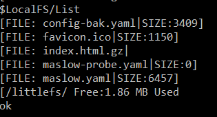
I loaded up fluidterm and tried to reupload index.html.gz and maslow.yaml manually, but get a failure mid upload. Ignore the file name, just trying to grab a representative screenshot.
I tried all combinations of install-fs, erase, and full install, but there seems to be something terribly wrong with the non-volatile storage. I am able to revert to 1.10 and have the same error.
You can see the result of the failed yaml upload. If I try to just CTRL-U a new maslow.yaml or index.html.gz I get the same error on upload and then it fails to show a file size in the listing.
I would recommend just running the Full-Install.bat again which should overwrite everything.
The “Error ESP_ERR_NVS_NOT_FOUND” isn’t a big deal. That just means that the machine couldn’t find a saved value for the z-axis position but that’s to be expected after a fresh install.
I was able to fix the fan cable when I reassembled the fan cover on the board. That does make a big quality of life improvement.
With a Windows 11 laptop the capture portal worked properly. I had been using an older Win 10 laptop in the workshop. I was able to do the full install of 1.12 with a USB cable and re-run the “Find Corners” routine. (As a side note calibration force in the settings menu and the terminal output of the Maslow itself still refer to the routine as calibration)
The “belt fighting,” waviness, oscillation still occurs when performing a test cut dry with the router off and the dust collector hose disconnected.
Would replacing the control board with one from the store potentially correct the issue?