The order that they go on is important. When viewed from the top of the router with the power cord down the first arm that slides on should point up and to the left, the next one should be down and to the right, the third should be up and to the right and the final one should be down and to the left.
It would be really helpful to have a series of four pictures, or a single image with a 2x2 grid, all shot from the same angle (straight down looking at the top of the router maybe) showing this sequence.
And you would be right. Thank you for catching that, I’ve fixed it.
Again, thank you great catch.
These kind of things would probably be easy for a native English speaker to catch, but I think that many people will be using google translate to follow the directions and a little mistake like that could be very confusing after being run through translate. Thank you!
This is a fantastic suggestion. I was trying to think of how to show that more clearly in a single photo and you are spot on, it should be four pictures. I will make sure we get those when we film the video for this section.
If you assembled it with an electric screwdriver or told people to just buy a cheap $4.37 2mm screwdriver, assembly would be so much more enjoyable. no one likes screwing around with those Allen wrenches
Assembly guide looks good. Only step that is not clear is towards the end. No pictures of how the entire assembly goes on the sled. Maybe a couple more phtoos to clarify how the supports and rods get connected. Probably obvious when it’s in front of you. Well done.
I worry a little bit about electric screwdrivers because the non-torque limiting ones make it really easy to break something. Most of them have a torque limiting setting and would probably work great, but it’s not too hard to strip the nuts out with one of the more powerful ones.
Excellent suggestions! I’ll get some more pictures there.
I’m working on a piece of paper that will be in the box with some safety warnings and directions for where to find the assembly guide, got any feedback on how this looks?
@bar looks like you’ve made great headway on the User Guide! One item that I’m curious about is the determination of X and Y related to the machine. At the Extend All step, how do you ensure that the machine is rotated correctly to match the entered .yaml guess parameters, especially for non-square work areas? Thanks! (hoping that this post isn’t too out of place in the assembly guide thread)
The router is free to rotate in the arms and it rotates around the router bit so the orientation of the machine isn’t important. That was one of the key lessons learned from the first version of Maslow which didn’t work that way.
The X and Y axis are defied relative to the lower left and right anchor points (the line between those two defines the X-axis). I could see in a case where the anchor points are really not a square at all that might be not ideal, but it’s a software thing so we can change it in a firmware update easily once we have a more clear understanding of how we want it to work.
I guess technically they are all interchangeable. The lower left one is just whichever one is down and to the left. If you run the calibration process with them hooked up one way and then hook them up a different way it’s not going to work, but other than that they’re arbitrary.
If they are arbitrary, how does it decide which direction X and Y are in?
(assume it’s laying flat so that it doesn’t have any help from gravity that
would let it guess)
what’s to stop it from thinking that the ‘top two’ or ‘left two’ are the bottom
left and bottom right and setting the axis based on that?
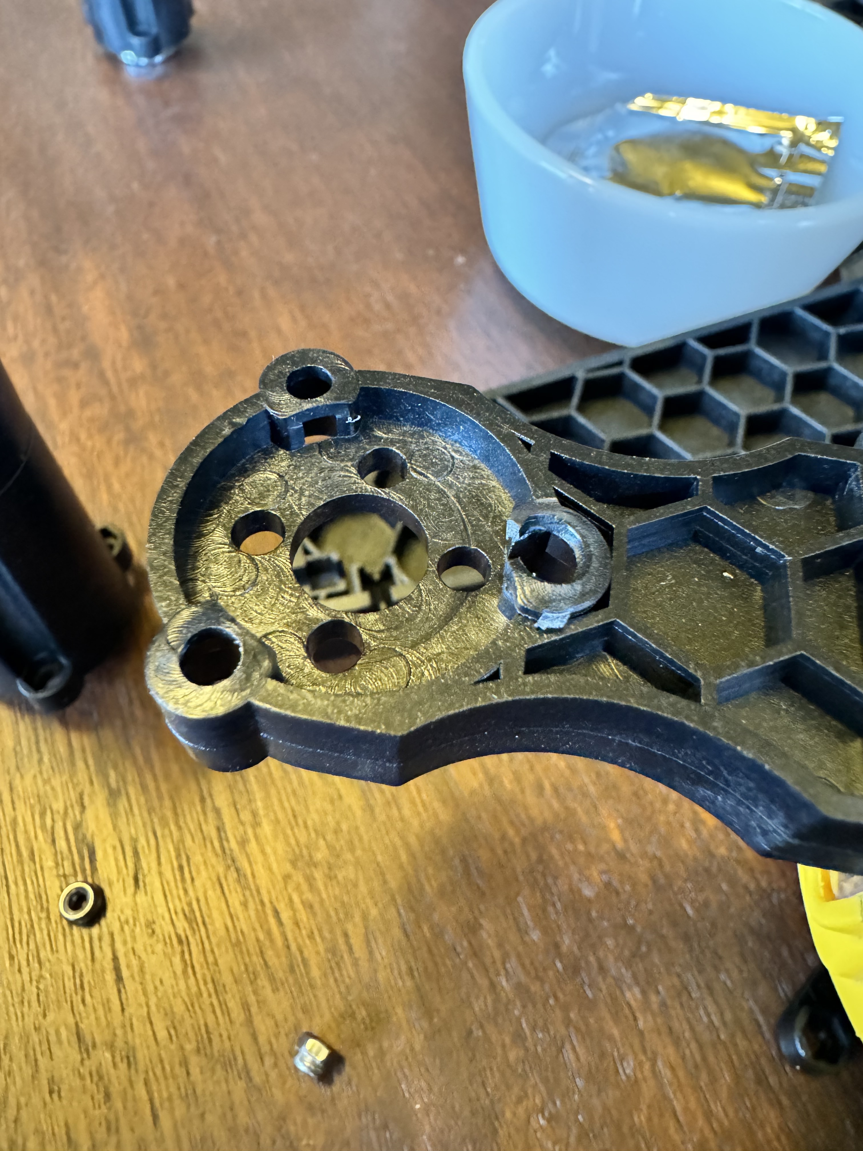
Feedback on the Router Assembly instructions (I think it’s also mentioned above). The instructions about attaching the uprights to the clamp definitely need fixing asap. The single photo and instructions are confusing about which posts the linear bearing posts go vs the non-bearing posts. I did not notice that two of the posts have insets for the bearings and it isn’t described in the instructions. I accidentally tried to attach a bearing post on the wrong arm and the result was that the thin shoulder holing the bolt head tore out. It would be much better to mention the inset for the bearing - if I would have seen that I wouldn’t have made my mistake.
Any suggestion how to handle the damaged arm? My only thought about how to repair immediately is to epoxy in the area and redrill the hole.
The easiest option is to send the address you would like it sent to to Anna@Maslowcnc.com and we’ll get you a replacement in the mail ASAP. If you don’t want to wait for it to arrive the two remaining screws are probably plenty strong to hold until the replacement arrives so you can keep going.