I received my Metal Maslow today. So I have been through this forum a couple times and I find interesting notes here and there, but really the build of a Metal Maslow is not covered in detail. I have spent a lifetime designing, building and commissioning custom engineered machines. So given I am looking at a forced “Covid-19” retirement, I thought I would take a stab at Maslow. The concept is intriguing.
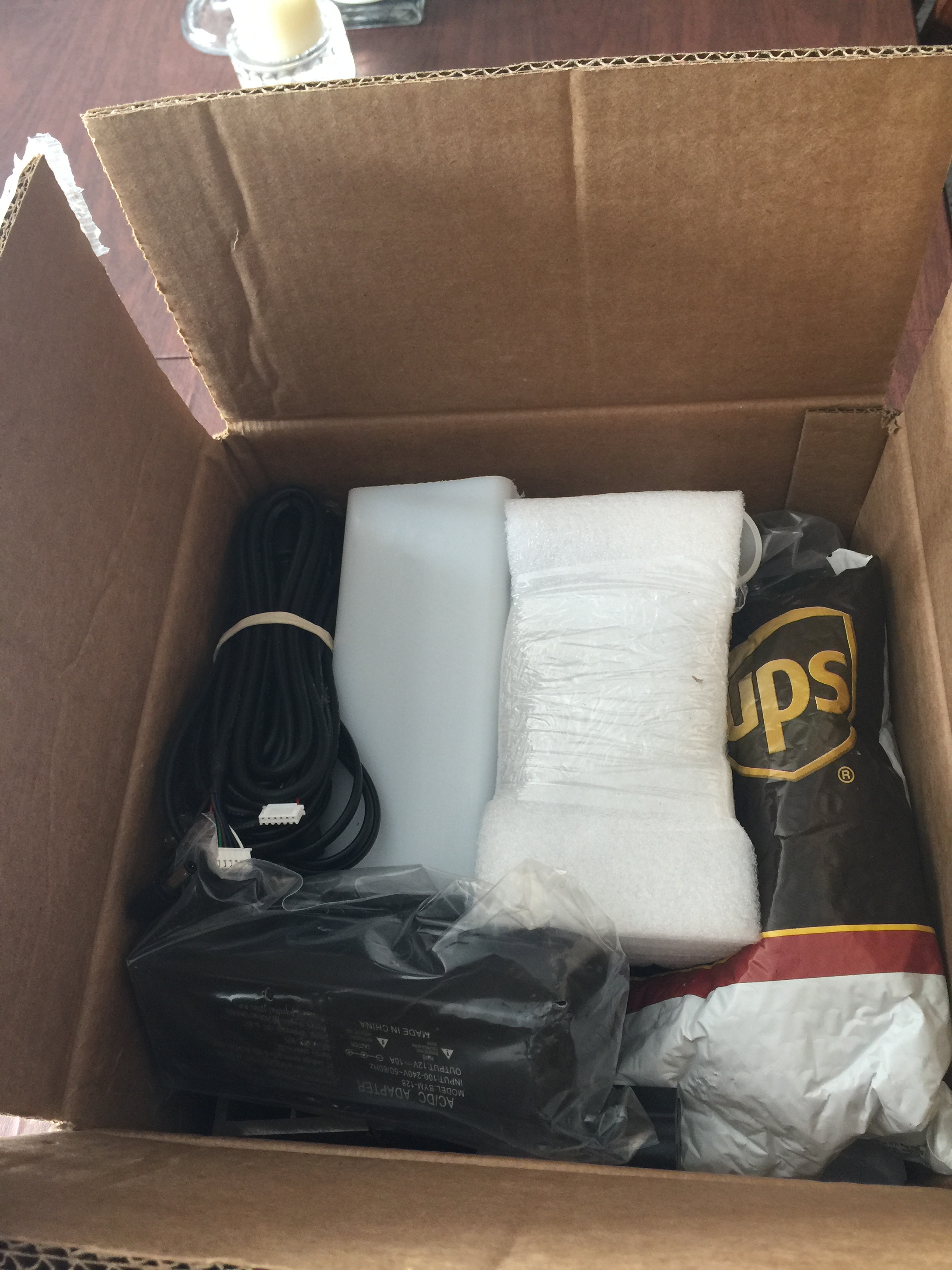
Todays delivery was a 25lb box of electronics and mechanical parts pictured below! There was also a nice note telling me where the assembly instructions can be located, web address of this forum and the offer of Skype or FaceTime support for the build of the sled.
I took a look at the online instructions. I have to say they are outdated, I have parts that are not listed in the instructions, so here I am contributing to the community with my personal experiences with a Maslow build.
Tomorrow, I will start the assembly of the sled…Look for the updates
Tagging along, I just got mine up and running two days ago. So far I am super happy with how it cuts, you will love it! It is definitely a DIY project, and the info you need is scattered amongst a handful of facebook posts, you tube videos and this forum. I’ve enjoyed the problem solving as I imagine you will considering your background. The best thing is the community of users who all seem willing to help.
If you have the space, go with the 12’ top beam and make it a foot taller than the plans call for.
I am working on modeling my frame as I assemble the mechanical components. So today I dug out the Main Motors, Motor mounting brackets, screws, and Motor interface cable for dimensioning. I notice a mark on the sprocket that I imagine is used during calibration. I also found a spur gear that maybe a spare for the gearbox?
Dimensioning was easy enough and if you want the cut sheet from the manufacturer, just search the part # stamped on the gearbox. ET-WGM58AE-1220.6.
Where:
“ET” is ETONM Motor
“WGM” is Worm Gear Motor
“58” is the Width in mm
“A” is a series
“E” is encoder
“1220.6” is 20.6 rpm at the output shaft @12VDC with No Load
What I cannot determine is the PPR of the Encoder…is it 3PPR, 7PPR or 13PPR? (anyone?)
The Brackets:
The kit is supplied with two motor mount brackets and (8)-M4 Philips Pan Head fasteners. The brackets can be mounted in two orientations (See Photos)
The orientation you use is driven by the frame design you employ. The down side to the orientation on the left is that the bracket motor mounting holes are countersunk on the opposite side. Using the Pan Head screws that are supplied on the wrong side of a countersunk hole will allow the motor to twist due to torque.(loss of accuracy)
The other choice is to mount the bracket to the motor as pictured on the right. (After I go buy flat head screws, of course.). This will make fine tuning sprocket-to-sled alignment more difficult. Also, I will have to carefully select the fasteners used to mount the motor/bracket to the frame. (See photo of Bracket for clarification)
I received my kit a few months ago. When I opened it up, I found a lot of pieces that hadn’t been mentioned and I had no idea their purpose. For instance, what’s that second power supply for? Oh, that’s a relay for the router, bonus!
One day while randomly browsing the forum, I ran across this thread in the Swap Meet category: Metal Maslow kit $600 ships Nov. Respond below if interested. A lot of the information you’re looking for is in this thread. It’s a bit frustrating that the best collection of information about the Metal Maslow is in the Swap Meet category rather than Hardware or Technical Details but such is the nature of a community like this - chaos feeds creativity.
There were a few QC issues - like your screw and hole mismatch above. Countersinks and counterbores were at inconsistent depths, the holes in the Z-axis sled needed to be tapped and there was some interference between the Z-axis sled and the linkage support. There are different size set screws on the same sprocket. But the system as a whole has been pretty well debugged so it saved a lot of time versus collecting all the parts myself.
I’ve been a little confused about various statements regarding the pitch of the lead screw. My kit contained a screw with a single lead with a pitch of 2 mm. Entering 2 mm didn’t work, the z-axis moved a lot farther than it should have. After some research, I found that the correct value for the z encoder steps per revolution is about 600. Using 2 mm and 600 it was really close, but also really, really slow. I discovered that multiplying both numbers by 10 retained the accuracy and sped things up a lot. The numbers I settled on are 20 mm and 6031 steps per revolution.
Space may be an issue with 12’. Will you share the advantages of increasing the motor separation and height above the work area? The benefits are not obvious to me. Thank you.
Jack
If its the same as the stock motor (which I think it is), then the steps per rotation value you put into groundcontrol/webcontrol is 8113.73. This accounts for both the encoder steps and the gear ratio.
Yes, this is because of how the firmware calculates maximum RPM. It was based on the original design and somewhat hard-coded. Your solution (multiplying by a constant) is the proper way to overcome the issue.
Because of the nature of the machine as designed, a heavy sled hanging on chains. It has a hard time cutting across the top center (tends to sag down when chains near horizontal) and in the bottom corners (not enough mass to swing it all the way out to the edge when one chain is almost vertical).
With the motors spaced further apart and a little higher up, it reduces these issues to almost nothing. If you plan on using the full 4x8 foot sheet of plywood, I would shoot for the enlarged frame. We are talking about millimeters here, but for me it was important to get the machine as accurate as possible out of the gate. You don’t really need much room on the sides or above, my 144" wide machine is in a 160" wide room.
the performance of the maslow in the bottom corners is limited by the force that
gravity can provide to swing the sled towards the outer edge. This is limited by
the angle of the chain. by moving the motor out, the chain gets more of an
angle, so gravity provides more force.
but when you do move the motors further apart, at the top center, the angle
between the chains gets wider, and you need more force to hold the sled in
place, which ears the gears more and may just run out of power and not be able
to move there. By moving the motors higher you reduce this angle, making it
easier to move the sled in the top center and reducing the wear on your gears.
moving the motors higher hurts the angle of chains in the bottom corners.
but going an extra foot out each side and a foot higher ends up being better
everywhere
there is a google docs spreadsheet that lets you put in different machine
dimensions and see the min/max forces and see how different machines compare.
Right at 93" tall, so it would be ok under a standard 8 foot ceiling. It is cutting great and I am totally loving what we are accomplishing with our metal Maslow, scratches and all.
it’s $580 plus $20 for shipping $600 total, and then you pay taxes, which are charged by your state not me.
original kit was $410 plus $15 shipping and $160 for the router =$585
so for $15 more you get a laser cut base and gantry plate, 10x faster z motor, c beam z axis motor. Arduino Relay power controller, longer chains, better counter weight, etc. If one does the math it is the cheapest and the most feature set maslow kit available. But yet time and time again I read that my kit is too expensive. I don’t get it. Perhaps it’s because other sellers don’t include the engine/router with the kit so the price looks cheaper?
sprockets are the same on all maslow motors from all 3 sellers, I’ve yet to read of any of them slipping. The set screw and flat face secure them well.
the z axis encoder is 3ppr.
the two L/Right motors are the same as the original which I think is 7ppr off the top of my head.


