I’m in the 212+ club as well, and likewise I think it would damage the support if I tried to use bolts to get rid of that gap.
Grinding them down is not my first choice, what are your thoughts on printing a shim? I see that at least one other person has done that, and someone else has fabricated a shim from materials on hand.
Is there a downside to this method, or should I buckle down and let some sparks fly?
I made shims from old credit cards, I thought it worked well, but after seeing other posts about distorting the sled I put my sled on a flat surface and realized I did have a bit of wobble. I just loosened all of the screws holding the rod supports to the sled by about 1/6 of a turn and that seemed to flatten things out. I need to check with a proper straight edge to be sure, though.
I will probably run it like it is for a while, if the nuts start falling out during cuts (already had two of the linear rod clamp nuts drop out) I’ll either re-do my shims or use some green loctite 290 on it. I’m also considering getting some 10mm linear rod stock and cutting it down to size, I can get 300mm rods and cut off 90mm with my bandsaw, that seems more likely to succeed than cutting 1-2 mm off of the rods I have now.
yep - I 3d printed a shim (actually several)
Handling multiple shims to pack out the gap was a pain. So try and print as accurate a thickness as you can.
I had the same issue as Richyread. But I think that Geertdoornbos’s 3D-printed base support and some of that extra crazy glue would be enough to fix the issue.
Except that, with some paint tape for holding some nuts and a two-hour afternoon, the build went pretty smoothly. The guide is now pretty clear.
I looked for a user guide feedback thread and came up blank but it might be bad searching on my part. In case it doesn’t exist, I’ve got a little one:
This might seem obvious to everyone else because I haven’t been able to find any messages where anyone asks this, but I don’t know if it matters which belt goes to which corner. The initial calibration and hookup part of the user guide doesn’t say anything I can see to this either.
My suggestion is that one way or the other, it would be handy to get a note about that. If it’s important which belt goes to which corner (which seems plausible) then a diagram or something would be cool.
I’m pretty sure I’m just the slowest horse in this race because nobody else is talking about this and I apologize if this is a ridiculous request.
Hi! In the assembly instructions there are a drawing, a gif and a YTvid about putting the arms around the routerbody, and in what order. What it does not say (anymore?) in the assembly instructions are the names of the arms.
But if you followed the assembly instructions carefully, the only thing you need to know when you put your M4 on the frame, is that the powercord and the vacuumhose point down, to the bottom of your workpiece. Then the arms point to the right anchors.
The problem with identifying the arms is that when you put them on the router, you are looking at the bottom (collet) end of the router, so your right arms are on the left and vice versa. It was confusing.
I’ve ground down 6 rods so far, all by 1.75mm to 2.5mm. They are supposed to be 210mm I believe. Took it slow on a vertical belt sander. Fit so much nicer when I swapped in the correct size. I’ve got 2 more to do now with my first build partly dis-assembled. I saw your photo earlier but hadn’t seen the tear in the corner brace! dang.
Tip: to get perfect quick alignment when pressing the linear bearings, use the rod to anchor everything i.e drop the first bearing over on the rod in the sled then drop the two-piece plastic assembly followed by the second bearing. Now they are all cocentric you can apply hand pressure to squeeze the bearings into place. It makes the assembly perfectly aligned and butter smooth on the Z axis.
In the step "press halves together( that’s seems to be the most tricky )…
In the current instructions, the assembly process seems easier when the belts are placed on the opposite side of the arms. Everything appears to be functioning well, but I would like to confirm if this is an improvement to the existing guide or if I have assembled it incorrectly.
I did mine that way and it’s working. I think only downside is sometimes the encoder gear with the magnet jumps out when it gets close to something to do its magic with.
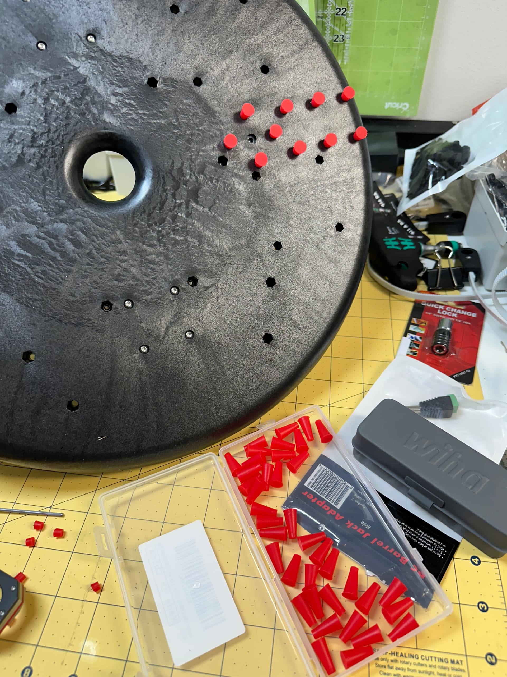
Here’s my latest speed run assembly tip. To keep the nuts in place during assembly, I’ve used just a finger, put in a 2nd screw upside down for the deep holes, and tried blue tape. What I really wanted during my first assembly was some little corks or stoppers.
I found these on Amazon:
And tried them out on my 2nd build, and was quite happy with the result. I had to trim them to different lengths for the different depth holes.
You have to experiment a bit, but I think I trimmed about 1/8" off to fit the deeper holes and still push the nut in far enough, and a bit more than that for the shallower holes where the lock nuts are closer to the surface. Ideally so that the net is held at the bottom of the recess and the plug is secure enough to flip it over.
Untrimmed they work in the support columns. On these I think I installed the nuts, then the plugs, flipped over and started the bolts, but then flipped again so that the nuts would drop fully down and not spin. Power driving from the top pushes everything down so the nuts don’t catch as well unless you have a really light hand with your powered driver…
If they were clearance drilled through the middle for an m3 bolt they would be perfect, so you have to be a little bit careful as you thread the bolts as they will push the stopper out and you can still end up with the nut not fully caught in the recess and spins.
Overall I had to fiddle with one or two that slipped out of the sled, but I was able to install all the nuts and then flip the sled and attach the top mounted parts.