Love your design. I literally just posted asking if a similar design that allows the sled to ride above the work surface would be feesable. From your video it looks like it is.
1 Like
I’ve just posted basic documentation Maslow-Mark-II-3D/ README.md
with upcoming updates.
Stay tuned
Tomasz
3 Likes
This is looking awesome! I would say for people without a welder/friend with a welder I love insert nuts. It’s a pretty cheap option too!
1 Like
how wide is your top beam?
The areas I would be concerned about are the top and bottom, where force on the sled would tend to make the gantry rack.
in the bottom corners where force is the lowest, how well does it move to the outside edge compared to the sled riding on the surface? (more mass to move, but possibly less friction).
It would be wonderful if you could space out stock to the right thickness and run tests of the gantry vs a normal sled (all else being equal). How much of your accuracy is in the rigid frame, proper alignment of ring/chain/cg, and how much is the gantry arrangement (and if you want donations to buy you material for your testing, speak up, I’d be happy to contribute)
when doing a lot of cutting, does sawdust/chips on the bottom rail cause any grief?
5 Likes
I think that test results (see above) and picture below addresses your concerns. I took this picture after cutting and putting sled into “resting” position. Part from lower bottom corner are cut as design +/-0.5mm - it is all what counts. About force distribution see my discussion with @madgrizzle above.
Dust is nonsense but fortunately material supporting angle bar at the bottom of workspace collects most of it - you must constantly clean it.

If I understand your question you asking for the width of gantry bar - gantry is 1644x432; see detail drawings in the Garden projects - Maslow MarkII-3D
3 Likes
A question and a suggestion.
How much did the build cost you?
For uneven surface it seems you could mount a sensor to measure the distance and offset Z in Gcode. You may have to add more negative Z reach in this design. It seems like there should be a way to do this in realtime.
Anyone?
Thank you
Why wouldn’t you just let it touch down somewhere on the backboard and work with positive z-axis?
Good question  I do not keep all my receipts so only very rough estimation:
- steel tubes - 10 pieces of 3m each 40mmx40mmx2mmm - around $120US
- carpentry angles - 16 pieces - $25US
- ball bearings - 22x8 - 16 pieces - $29US
- self taping screws - ~200 - $20US
Please do not quote me - $170 - $200 is my best WAG.
I am not counting cost of Maslow kit, computer, AEG router, router bits, workspace timber, blocks for tensioning chain slack, etc. It is very hard to guess cost of printed parts - it is separate topic. I did not trust completely the mechanical strength of my parts. As you see I used steel angles on top - just to be safe.Printed parts doing excellent job in setting ball bearings axis and aligning steel bars but strength - I do not have enough experience. We will see…
4 Likes
Please try the zipper tree challenge! 
1 Like
Good idea but there is only 24hr a day - priorities, priorities…
Do you know where I can find dxf file with that pattern?
Tomasz
If you asking for workspace width - it is 3000mm see drawings in the Garden project.
I don’t, but maybe @c0depr1sm can share ![]()
Great job on the gantry! I was thinking of doing the same idea. I have a good true sturdy frame to start with
. Your tubing is 40mm which converts to 1.575" but here in Canada I could only get 1.5 in. My question is would the printed corners and roller brackets adapt to that size? It’s about 2mm smaller so I’m sure the bracket could be shimmied but is there adjustment in the guide rollers?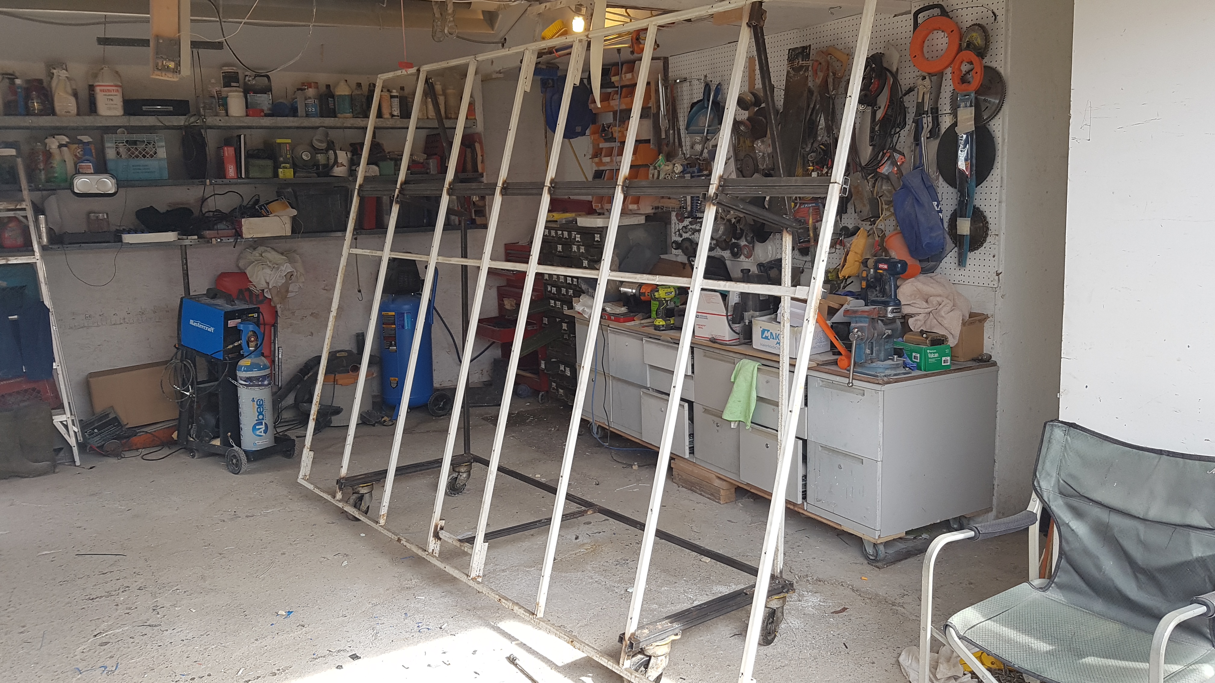
2 Likes
Great stuff Robert!
Guide rollers (as you call it - I call it carriage rollers) are independent of tubing dimension - carriage will ride just 2mm lower. You can compensate it with workspace hight.
The corners for gantry will accept 1.5" tubing - I made oval holes on the outer side to allow adjustments in X and Y. The bottom holes (also shifted to outer side to clear ballbearing axis) are used only after final adjustments when you committed to distances. Keep in mind that gantry literally hangs on top bearings and lower guide rail is just a support.
Very important is sequence in which you constructing gantry and carriage - I started with assembling carriage’s three corner rollers; set gantry width to carriage width; add fourth roller corner to resulted width; committed to dimensions by tightening side screws, screwing bottom screws and reinforcing corners with metal angles. My carriage is 340x340 and I suggest at least 15mm thick plywood for stiffness. The beauty of design is that XY tolerances in gantry/carriage do NOT translate to error in cut - cutting error depends only on Maslow arrangement. Router bit position is driven by chains length. Error in Z depends DIRECTLY on accuracy of gantry/carriage assemble.
I am now working on circular saw adapter for ripping and cutting so keep this option open when building your frame.
Good luck and let me know about your progress. Glad to be of help to my fellow Canadian
Tomasz
Hi @TomD and @WoodCutter4,
Actually, I shared one of the SVG file in the Zipper tree Challenge post.
You can right click and download the file!
The whole thing is however quite big and requires more plywood than necessary.
So I definitely suggest those who would like to take the challenge to adapt it ![]()
Ah, I didn’t notice it could be downloaded. I thought maybe you forgot to attach it in the OP. Considering the source, I should have know better  My mistake.
Also, I see it is only one “branch” of the zipper tree with other branches being slightly different shapes? How did you create the *.nc file? Any change you would be willing to share that too?


Hello Tom,
Wow…that looks like it was a lot of work. I am just wondering one thing about this build. You practically already have a full gantry style CNC machine here and you say it only cost you about $200 more than the maslow and router itself. So why are we not building true style horizontal gantry system for that money and be done with chain slag and inaccurate cutting in the corners…Just my two cents
a coreXY approach would be FAR better than a maslow hanging approach, grbl
with steppers would work very well, servos could be made to work with
modifications to the new code that’s being discussed (the version 2 grbl thread)
David Lang
So are you saying I am correct with my assumption?
Space constraints come to mind. I suppose you could up the torque on the steppers, though. That said, it’s a good question
1 Like