you guys paint me as some kind of nice guy…I am just doing this since I have not yet assembled my Maslow yet (my girlfriend is half Italian and will kill me once she sees it in our garage) and will need some help tweaking it…
So poor Tom will get a LOT of emails from the USA asking for help
Tom, now that you have these nice smooth rails that your sled is moving along on, could you add some optical encoder to the X and Y axis and get really accurate positional feedback from those? Or is this overkill?
Nah, she won’t kill you. You just need to set aside time to go outside in the driveway, let her yell at you over the top of the car, while you two take turns slamming the car doors at each other for emphasis.
Sounds like a carefully-considered gift to your girlfriend as the very first project made on your Maslow would be a good idea. You would not be the first Maslowian to do this.
Sorry Aymeric for long delay in my answer - I must missed your question.
I do not see how knowing exact position of gantry will help. Maslow calculates length of chains for every g2 code line. What you will do with linear encoders signal?
In previous posts I tried to explain my understanding of Maslow “guts” and I think that it is worth to reiterate at this point:
“Imagine distorting whole table - squash two opposite corners but keep top and bottom beam parallel, squash gantry and carriage the same way. Gantry and carriage can still move freely although local XY of table/gantry/carriage are no longer orthogonal.
What Maslow’s software see? What happen when Gcode commands to cut a vertical slot? Will slot be vertical?
That’s the beaty and elegance of Maslow design - source of error is only one: the length of chains. Slot will be vertical - gantry and carriage only supports router. This is just different type of sled - nothing more. I need exactly horizontal top beam ( the one with motors) so gravity works with me and left and right chains are stretch correctly. I need top beam supporting gantry to be horizontal to minimise forces for gantry movement. I really do not need lower beam supporting gantry to be horizontal as gantry just roll over it (making it horizontal minimize friction of gantry movement).
So adjustment of Y really does not matter and it is enough to rely on gantry bracket to keep it square.”
In my opinion encoders will be overkill
Cheers
Tomasz
I do not see how knowing exact position of gantry will help. Maslow calculates
length of chains for every g2 code line. What you will do with linear encoders
signal?
the maslow knows how much chain it has let out, it doesn’t actually know where
the bit it. It attempts to calculate this based on the amount of chain let out,
the weight of the sled, etc.
If we had accurate x/y coordinates, it would let us adjust the chains to get the
actual position instead of the estimated position (assuming that there is not
too much sag in the new encoders)
In previous posts I tried to explain my understanding of Maslow “guts” and I
think that it is worth to reiterate at this point:
"Imagine distorting whole table - squash two opposite corners but keep top and
bottom beam parallel, squash gantry and carriage the same way. Gantry and
carriage can still move freely although local XY of table/gantry/carriage are
no longer orthogonal. What Maslow’s software see? What happen when Gcode
commands to cut a vertical slot? Will slot be vertical? That’s the beaty and
elegance of Maslow design - source of error is only one: the length of chains.
Slot will be vertical
the trouble is that the effective length of the chains depends on a number of
things that can have error in them. The slot will be vertcial if you are in the
exact centers between the motors, if you are anywhere else, it may not be
vertical
In my opinion encoders will be overkill Cheers Tomasz
possibly, I question the actual accuracy of them as well. But it’s worth someone
trying it.
This thread has made for really fun reading for me. I have not managed to build a Maslow or any other cnc yet, however i have really enjoyed getting my head around the concepts so far.
The attraction of some form of x y location system (magnetic encoders for example) is that it should take the “guess work“ out of where the bit actually is. The code could use it as a continuous feedback and adjust chain length to compensate for chain sag.
The issues would at least be 1. that the x y location system as well as the rails for the sled would have to be very precisely set to have the x and y parts at exactly 90 degrees to each other. The rails would have to be very flat and smooth too. These are things other cnc system have to worry about but Maslow currently doesn’t. 2. The chain sag will still define an aspect of the error. With a 100% perfectly flat/smooth rail and track system that is set to exactly 90 degrees, the chain sag will still reduce the precision resolution by what ever factor we already have. We would know we were off but not be able to guarantee a good correction.
Still, it’s definitely very enticing to think it’s worth exploring.
I’m curious about how far a cost effective cnc system can go with a rail system built out of steel like this one or using steel framing studs. Still on edge at 15 or so degrees so that only one long beam needs to be so perfect. Some sort of fine adjust to help get the gantry part at 90 degrees to the horizontal beam.
Magnetic encoders for x and y positioning would mean the drive system could be less complex, though it would still need to give very precise movement. Spring mounted rubber wheels running against the horizontal beam could do it for example.
Finding accurate enough, low cost, encoders would be one challenge.
What is the flatness factor of steel framing studs or the steel box section used here. ? Can It be run through a table saw type set up to correct it enough. ?
Sorry if my comment is not exactly contributing to the original thread. Hopefully one day I’ll be able to prove out such a concept myself. Keep up the amazing effort.
look up MPCNC and lowrider 2 CNC they are cheap ways to make a CNC with cheap
rails and printed components
accurate rotory enocders are cheap, when looking for distance encoders, watch
out for the error, a 0.1% error sounds great, until you think about measuring
over a couple thousand MM and looking for <.5mm of error.
YAHOOOO!!!
Part arrived! Thank you Aymeric! What a joy - it signifies community strength in global village and power of technology: something design in one part of the world can be manufactured/printed in another.
I am amazed by quality of the print: take a look on my PLA print and compare with Aymeric’s nylon with carbon fibre:
My Maslow is ready for action! I am planning to restore sailing boat over winter months. There will be a lot of plywood cutting. I also will replace daggerboard and rudder so 3D machining will be required - good test how Maslow will cope with shallow 3D and 2.5D operations.
Once more - big Thank You Aymeric - I own you big!
I’m finally getting around to getting parts printed for this and I wanted to confirm that a “kit” would be:
pilaSupport - Quantity 4
xyBracketLeft - Quantity 2
xyBracketRight - Quantity 2
In addition, I’m using an online 3d printing service that offers a pretty broad range of materials: Based on previous discussion, I’m tempted to go with Polycarbonate as it seems to be the strongest among the choices… I’m open to other suggestions…
Which service did you end up using? I’m in the middle of both an SLS 3D print projtect and an aluminum CNC milling project with Xometry to try them out. I’ll be posting some photos in the next few days on this thread: 3D Prints for those of us without 3D Printers - Xometry Review
Has anyone pursued this design yet? I am hoping to weld up a frame in the next week. Would love to hear if this works or not as it would be far simpler and more accurate.
What are the measurements of the carriage? Are you still doing the Maslow chains and sled or are you starting to convert towards a Cartesian setup with the sled traveling up and down the carriage and then back and forth across the field?
Would love to see photos and get some details of your build.
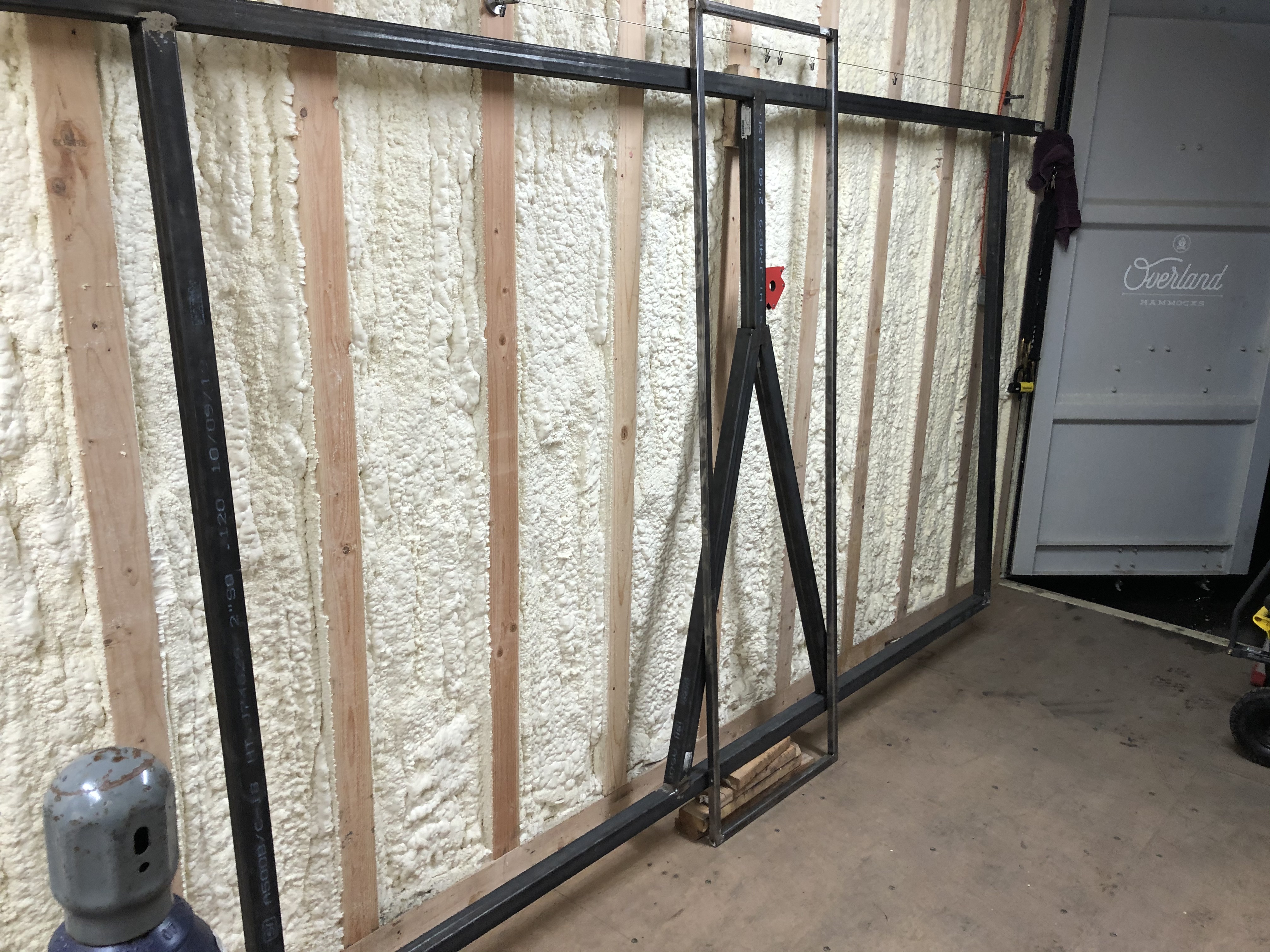
I have been working on building the frame for my attempt at building a Maslow Mark II and panel saw combo. It has an overall dimension of 12’ X 7’ which is a little larger than probably needed, but it provides some flexibility on what I can cut. I should be able to cut a full 5’X10’ sheet using the more cartesian focused gantry and sled as was depicted above by jwolter.
I have designed new top and bottom brackets and can post those if anyone is interested.
Here are some images from a fun night welding up the frame in my shop. 2" cold rolled steel for the overall frame and 1" square tubing for the gantry. Sled will be produced tonight so hopefully I will have a “rolling chassis” this weekend.
Much work to do to get the drive mechanisms designed, mounted and functional, but progress none the less.
Way to go @MakerMatt !!! Welded frame looks simpler and stiffer. I love your design of raised brackets - looks that you’ve gained good 50mm in z-axis. Will you use tube to hold gantry together? I do not quite understand function of the bracket depicted in first picture ;-((
I am keeping my finger crossed for you - keep us posted
Tomasz