Beginning workings of the sled and z-axis setup. I got the sled laser cut from steel and am working on getting a c-beam z-axis planned out. Cutting out the sled was surprisingly affordable, only around $20. Hoping to have the sled assembled here in the next few days and hopefully cutting very soon
Edit: For anyone who is interested, I got the sled cut by lumberjack1983 on eBay. I just messaged them and told them what I wanted, and they made a custom item for me to purchase. The turnaround time was 1 day. Shipping prices were very reasonable as well, only around $12
I would love to @cmullins70 but unfortunately I bought these made for the ridgid router since I don’t really have a way to make something like this myself. These are the guys I purchased the set from. I had them machine it for a 92mm hole and it’s a perfect fit and they made it and shipped it the same day I ordered. If you email them directly at chrisclub@gmail.com, their flier indicates that they might be able to do it for a bit cheaper.
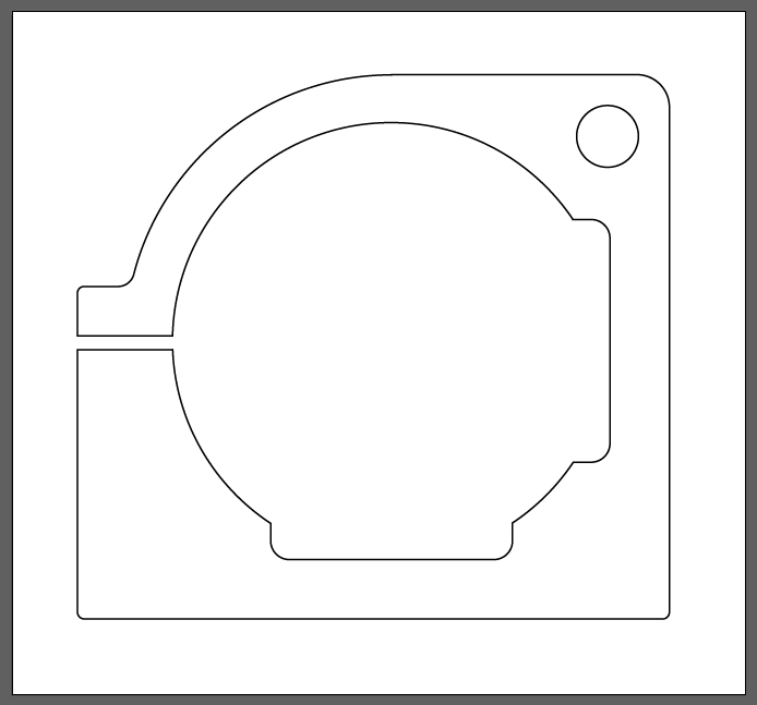
If this is helpful, I sketched up the design in Illustrator for planning out my sled. I don’t have a traditional CAD software at the moment, but this may be useful for someone out there.
Made a bit more progress, hopefully people don’t mind seeing all these incremental photos. Got my Open Builds linear actuator as well as the stand off plate set configured together with the Maslow z-motor. This required cutting a thin piece of aluminum to mount the motor to the stand off plate since it’s designed for the NEMA stepper motors. I shortened the c-beam from the kit down to just a hair under 200mm long and re-tapped the holes on the cut side. This combo is a bit pricey, but honestly in the time I think it will save in troubleshooting and testing out various z-axis configurations I think this is the way to go.
For dust collection, I took the concept of OTandAT’s 3d printed base and did a redesign for the hose configuration I plan to use, as well as some other tolerance adjustments. This is designed to attach to a 1.5" ID vacuum hose. For those that have not heard of it, I’ve been doing my 3d printing lately on Treatstock which is incredibly cheap compared to large printing services. I’ve used several different makers with excellent results each time.
@mhnudi Your design choices, build quality and speed of progress are impressive and have been exciting to watch.
As far as incremental photos etc, some people start their own topic to document all aspects of their specific build or add on to other existing, relevant topics. One thing that is so great about this forum is the massive amount of information but sometimes it can be hard to find what you are looking for. It is helpful to try to stay on-topic and post other information on a more relevant thread. I hesitated to say this because I don’t want to discourage you or anyone else from sharing or posting (especially when your posts are so well documented!). For example, there are a lot of z-axis modification topics that would benefit greatly from your post about where you got the parts.
Thanks @Keith & @WoodCutter4. I had no idea you could switch out the title, so I went ahead and changed that to something more appropriate to what this thread has become. My goal when I’m done if everything works out as I hope it to kind of summarize the build and things I would do differently, as well as provide a summary of all the sled files, 3d prints, etc I used, either from the community garden or homemade. I was picturing that once I have a completed system I could sprinkle my experiences around the forum in the appropriate areas. Thanks for the feedback!
I would be very grateful if you pull together all the files and links to the suppliers. I’ve learned a lot in your thread so far and the quality of the work is really impressive. Please do that consolidation document and links when you are done.
I will be very interested to see how your calibration goes and what your accuracy and repeatability is. Are you going to use holey calibration or stock?
Wanted to post a brief update on the sled progress after having to wait a while for various parts to get shipped to me. The sled is 16" diameter, made from ¼" steel. Hole placement was laser cut, with holes drilled out manually. The perimeter is “Style 3” UHMW trim from McMaster-Carr. I left a small gap at the top to hopefully prevent a vacuum suction condition on the sled.
Most of the holes were tapped 6-32. The c-beam is mounted through the steel with the low profile bolts counter-sunk on the back side. I used these 80/20 support brackets to further secure the c-beam to the sled.
Early tests outside of GC seem to run very smoothly. I may end up gearing it up eventually but for the time being it’ll do.
Not sure you needed those, but it certainly makes it stout. I screwed my c-beam through 1/8" steel with flat head m6 screws and it seems very rigid. If you find you need that space where the support bracket is, I am sure you can take it off.
I really like your orange guard/guide around the bit.
I probably didn’t actually need them, but I will say that I think that small amount of extra weight seems like it will be helpful on the bottom of the sled. It’s not obvious from the photo but the center hole of this sled is offset vertically about 1.5".
The orange part on the bottom is the dust collection shroud. Here’s a picture with it attached to the 1.5" vacuum hose. It was tricky getting the port exit just right so it cleared the linear rail plate for the router attachment, as well as the ring kit rollers.
wow. again, your design choices and build quality are impressive. If that is any indication of what you are about to make with this machine, I’m excited to see it.