I’m waiting for a design thick enough to have bearings in the holes. My question how thin steel bolts can be to withstand the shearing force of a 15kg sled (+30% security) was never answered and I can’t calculate that.
That would be extremely easy to do , instead of 1/2" metal use 1" or 1.5" metal bar
or you can just use a bigger bolt like 8mm instead of 6mm. The shear strength of bolts that size is 35,000 psi

1 Like
Thank you @aluminumwelder for the picture. I’m getting closer to what I have in mind.
Using bearings the inner diameter determines somehow outer diameter and I want to go as small/thin/light as possible. I have a bunch of bearing that fit a 3 mm screw, the shoulder bolt is a great find that I missed due to lack of technical English.
I fond this bolt McMaster-Carr but I’m unsure about the shoulder length for 2mm thick steal arms. Still need washers I guess.
The shear strength is the same as for 8mm bolt so it’s the material strength that still needs to be applied to the diameter/ square-footage. I found this calculator Bolt or Pin In Single Shear Equation and Calculator | Engineers Edge | www.engineersedge.com that also takes the arm thickness in to account.
I just can’t put it all together. Either I’m getting to old or I’m to burnt out from the job. I even fail of figuring if for the top-mount kit the shear force is divided by all bolts or just on the middle 2 attached to the sled. I need help or have to wait for a more sunny day 
You are over thinking it. The whole machine is being held up with tiny chain links
any bolt will be strong enough and not shear apart. 3mm will work fine
1 Like
for the four horizontal parts, you are correct, drill them together and as long
as the bit is straight, they will work. What matters is the holes are matching,
not the exact dimensions.
for the vertical parts, the key thing is that all three holes need to be inline,
but the two holes at the top (and the only two holes for the center support) can
all be drilled at the same time.
the notch diemensions aren’t critical, you just need the chain to clear.
the horizontal bars can be made any lenth, 5" clears the stock router, 7" clears
just about anything
David Lang
I sent with stainless so that there was no rust to deal with that could cause
the arms to stick instead of rotate cleanly
1 Like
google ‘shear strength of bolts’, first link is
Using a .250-inch diameter grade 8 fastener gives you the following shear
capability:
A = Cross-sectional area of the fastener size (since bolt bodies/shanks have
circular cross-sections, use area of a circle) = Pi x r2 where R (radius) =
.250/2 = .125, therefore A = Pi x (.125)2 = .0491 square inches (in2)
Capability in shear = 91,000 lbs / in2 x .0491 in2 = 4468 lbs
Using the same .250-inch diameter grade 5 fastener results in the following:
Capability in shear = 75,000 lbs / in2 x .0491 in2 = 3683 lbs
66 pounds of tension from each motor just isn’t an issue.
1/2 diameter is 1/4 area, so a 1/16 bolt would have a sheer strenth of ~230
pounds
David Lang
2 Likes
the pins in the chain are 2.1mm (3/32")
Makes sense, and pretty easy to get the holes in line, just scratch a line and use a metal punch.
drilling a small hole like the 3/32 hole through multiple layers is non-trivial.
Just drill through one layer and use that as template to mark second bar. With the money you save over getting it laser cut. you could buy a cheap drill press. Not saying people should do it this way just another way to do it
@dlang Thanks for the fast shipping on this. It would be helpful to ship the kit with some instructions or a link to some instructions, I just ended up here which is good enough. Anyways I’m impressed with the pieces and have started getting things together.
I like that the pantograph kit is positioned to the sled according to a center hole. I did find the instructions on this page difficult to follow and it’s probably my fault there. I found the Onshape drawing very useful and correct me if I’m wrong but doesn’t positioning of the pantograph 2x4 mounting holes just boil down to the following drawing?

Yes, that looks right (and looks like the measurements I’ve been telling people have been wrong, oops)
It may be too many years of watching “this old house” and “new yankee workshop”, but I really try hard to use the story-stick approach of ‘put the small hole at the bit and drill through the part’ rather than measuring. That makes it so that people don’t end up translating from imperial to metric and if the parts are the wrong size (as long as they are consistent), everything will still work.
1 Like
I ordered a kit from David Lang earlier this year and just now getting it put together. I will update progress with the pantograph installation here.
@dlang, correct me if I’m wrong but I believe this is the way you described assembling the linkage? Of course, this is just a loose, temporary assembly.


almost, the center bar should be between the two horizontal bars. the way you have it they horizontal bars will pinch a bit (the center ends are closer together than the outer ends)


exactly. Now you just use one of the side arms to drill the holes exactly
corresponding to how your router mounts to the sled, and tighten the nuts so
things don’t have play, but move freely (which is why the kit uses nylock nuts,
the next ones will include only nylon washers)
David Lang
1 Like
More progress pictures (note uploading pictures from a phone doesn’t work well…can’t see the image after uploading).
This how the bit looked poking through the sled. Note the router is mounted to the sled and the sled is flipped upside down. I put the small hole at the bottom end of the arm on the tip.

I clamped one of the vertical arms (looks like a hook) to the sled and positioned it so that the little hole in the hook end is centered on the router bit.

I then drilled through the sled. I’m planning to run bolts through the sled to mount the linkage.
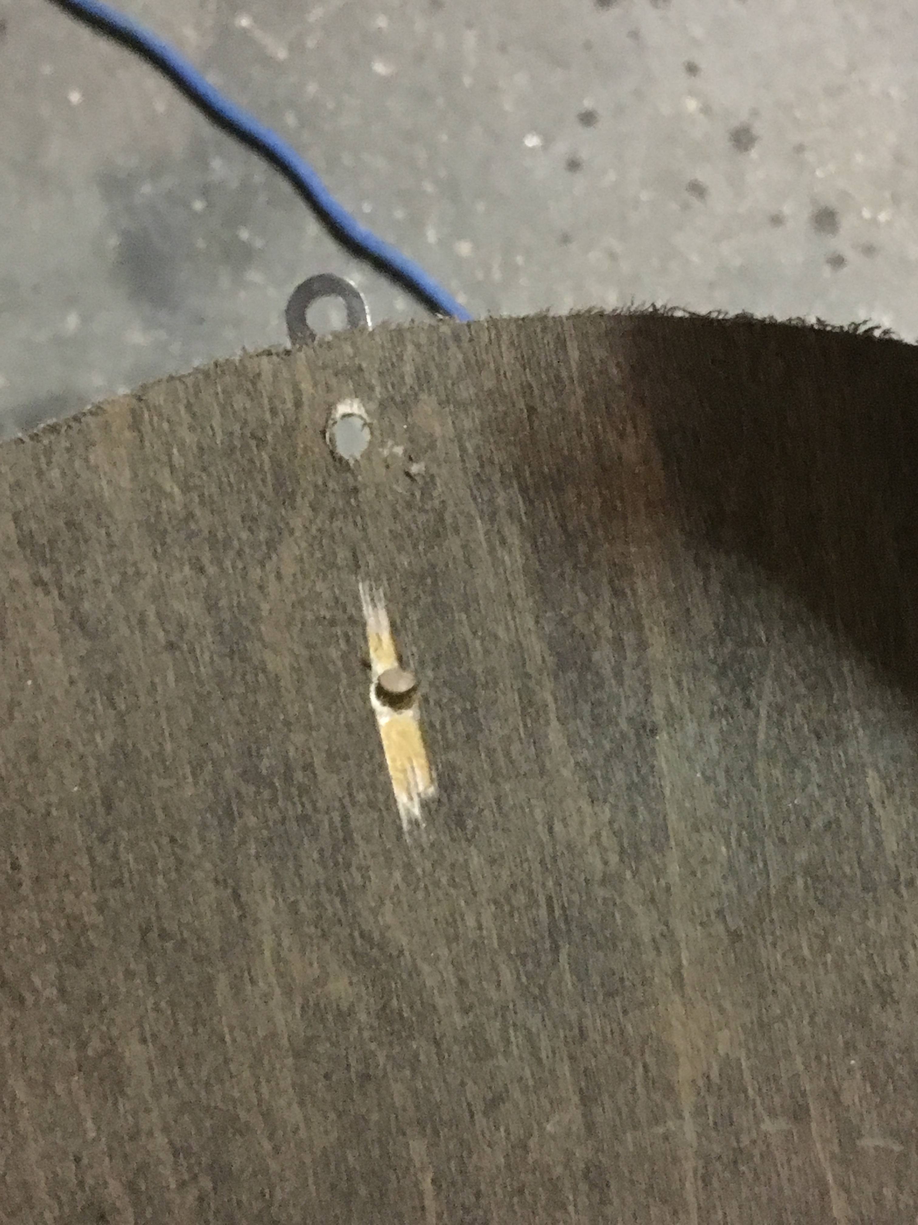

Since the linkage needs mounted a few inches off the sled, I’m going to try a 2x4. I clamped the wood to the sled and drilled some pilot holes in the 2x4 to mark the linkage mounting location. NOTE: this 2x4 will be cut to 2.5" once the holes are drilled on the drill press.

I hand drilled the holes through the sled but I am going look into redoing this on a drill press so that the drill goes through the sled and 2x4 at the same time.

12/27/2018 Update:
Once I got the drill press, I looked into drilling new holes through the sled and 2x4 but it was too complicated to get everything all clamped together and drilled so I just continued drilling the pilot holes I made before.

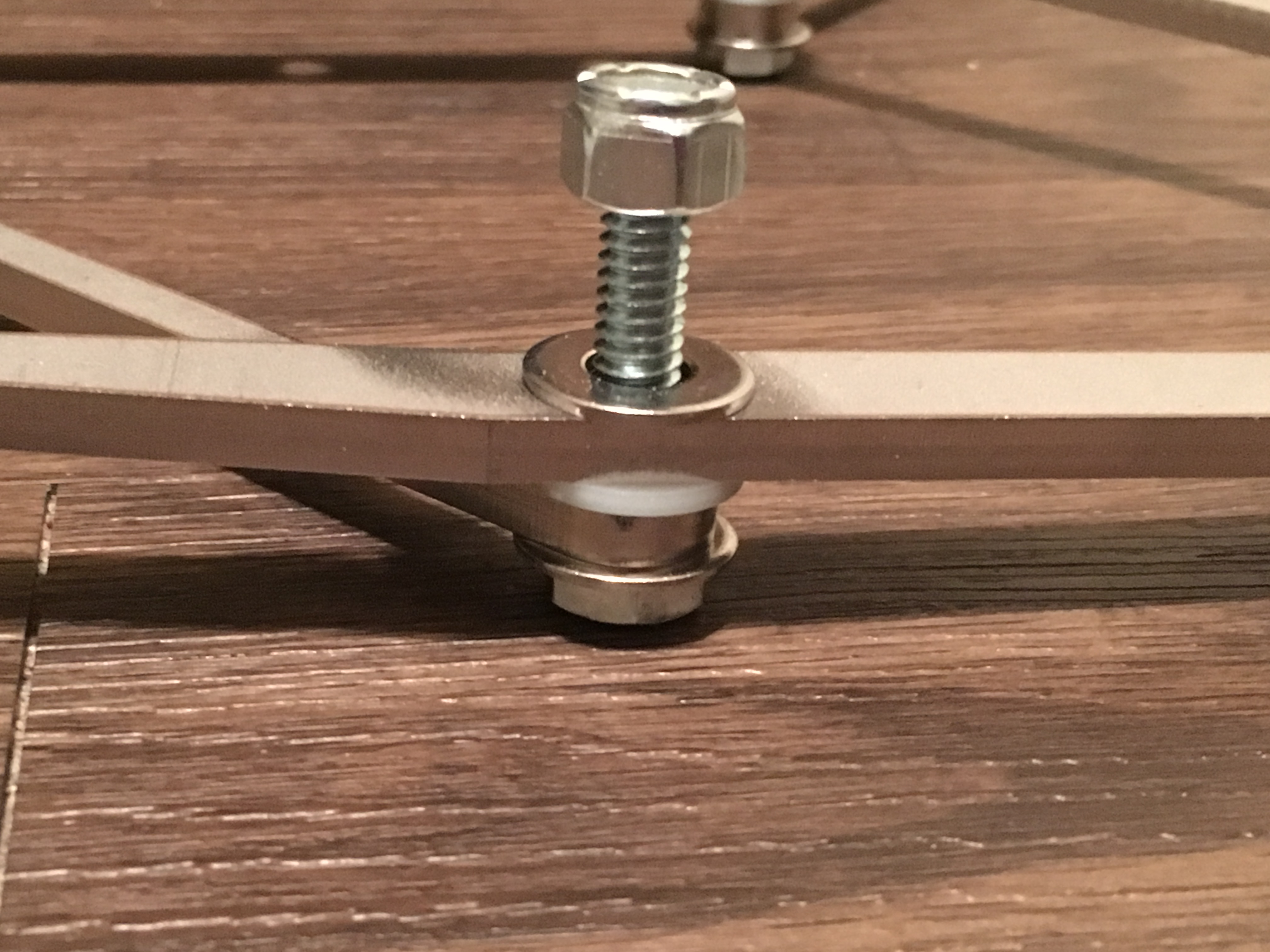
I drilled out the bottom of the sled to counter sink the hex head bolts.

I did not have problems with the bolt heads spinning.

I cut the 2x4 block a bit smaller, per @dlang, and mounted the linkage. I put some washers on top of the 2x4 and lock washers on top of the linkage center arm.

I then used a hole saw to cut out the center.

I still need to add bricks, tighten up the linkage bolts and cut and mount the 1/8” sheet of HDPE to the bottom of the sled but.

Feb 11, 2019 Update:
I’ve been trying to improve accuracy (that is for another post) and decided it was time to catch up on documenting my installation. Completing the sled construction…
I eyeballed the brick placement which, in hindsight, isn’t a good idea.

As you can see, the weight is not balanced and causes the sled to rotate to one side. If the balance is really out of whack, I think this can cause issues with the linkage in the corners. I believe the center bar should always remain vertical (or at least more vertical than this).

After moving the left brick so that it is mirrored to the right brick, the center bar looked pretty well vertical in the extreme upper left corner:

If installed accurately, the bit should stay in place while the sled is rotated. @Jay_Settle pointed out to me that I should perform a “rotation test” to verify the accuracy of the installation of the linkage. With the sled connected to the chains, and centered on the work piece, I plunged a 1/4" bit down about 1/2" into a piece of plywood (via GC z-axis controls). Holding on to the router handles, I slowly and gently rotated the sled clockwise to about 45 degrees and then back to center; the bit stayed in place. From center, I moved the sled counterclockwise about 45 degrees and the bit moved down and to the right as you can see in this picture. Since I’m using my hands, it isn’t a scientific test (I could have unknowingly pulled more vertically or horizontally at any time during the rotation). However, I do think it is an indicator of the accuracy of the installation. I’m not sure I can do any better.

I would do this after actually mounting the router to the sled, so that you are really sure where the bit will be (and if the sled ends up slightly out of position, the linkage will still be centered on the bit)
I think that’s one of the advantages of @dlang’s design. I think many people’s calibration issues are related to the router bit not being perfectly at the center of rotation of the triangulation kit.