I’m new to open source, arduino, python, cnc etc and this has been fun and I’m very impressed with this community. Before starting this past November, I spent weeks reading the forums to figure out what the latest knowledge and best practices were. This build is a compilation of some of that reading as well as things that others have done that I found clever and interesting.


I ended up compromising on some design elements based on materials I could find and the constraints of my garage space. The fact that I don’t have enough support on the left side, and the supports I do have aren’t aligned and symmetrical with the work area bothers me (so does the condition of my garage walls!). If I removed the window trim I could have added another support on the right side of the window frame but the hinge would have hung out over the glass a bit and I didn’t want to mess with it. I thought about mounting the machine so that the window was in between supports but didn’t want to obstruct the window. Also, my work bench and other tools are just left of the window. Obviously, the left side needs more support. I’m still thinking about how to do that with how its mounted now…Any suggestions?
I found some long, 40 x 80 mm 80/20 at my office and the boss let me take them. I was planning to use strut channel until I found the 80/20. My “frame” is really just a 3/4" sheet bolted to the 80/20 rails.

The 3/4” sheet of plywood acts as the waste board and provides rigidity (machine screws are counter sunk into plywood). A 10’ 2x4 is screwed into the bottom of the plywood, and 80/20, and extends 1/4” in front of the 3/4” ply to hold the work piece. Pros: simple, less parts and weight than a full blown frame and the sled will not bump the 2x4. Cons: The plywood could warp and cause the surface to be slightly uneven since I don’t have a true frame. I realize now that I need an additional waste board (don’t want to take this one off!) which means my 1/4” lip is gone, and I’ll need to rig up another one. I might try adjustable dowels like @Jamtek has done. Of course, there are some other good ideas out there that I am looking at. What do you use?
I saw other hinged frames and I wanted to have the option to park in my garage. I ended up using 10” strap hinges with 3/8” lag screws into the studs and 3/8” machine screws through the 80/20. I drilled a couple new holes in the hinges to fit where I needed the bolts/screws on the 80/20.

.
I used 1/4” brackets, bolted through the rails, to hold the square 80/20 in place. I had to use the smaller bracket on top so the strut could slid back far enough for a 1/4” work piece. In case anyone is wondering, the top bracket is just as important as the bottom!

.
2x4 legs rotate to allow the everything to fold flat. Pros: space saver, less parts and the angle is easily adjustable with sheets of wood (I started with 12.5 degrees, but have it shimmed out to about 15 to test the difference). Cons: I’m not sure that I will end up folding it back against the wall much and you can’t store anything behind it if you do want to collapse it. The hinged legs are not strong enough to support storage on top of them.

.
The Top bar:
A 20’, 12-gauge strut channel (ordered from Grainger) was cut to 12’. It can be adjusted quickly and easily along the square 80/20 pieces (found these at work too!) to ensure the chains stay perpendicular to the work piece.

.
Due to insufficient support of the top bar I had a very small amount of flexing and quite a bit of twisting of the strut. I bolted a 2x4 to the top of the strut every few inches and that took away the twisting. During the “pull chain tight” part of calibration, I could see the left side of the top bar pull out, in the z direction, about 4 mm. I’m not sure how big of a deal that is since the “pull chain tight” action is a lot more force that normal operation (right?)…thoughts?

.
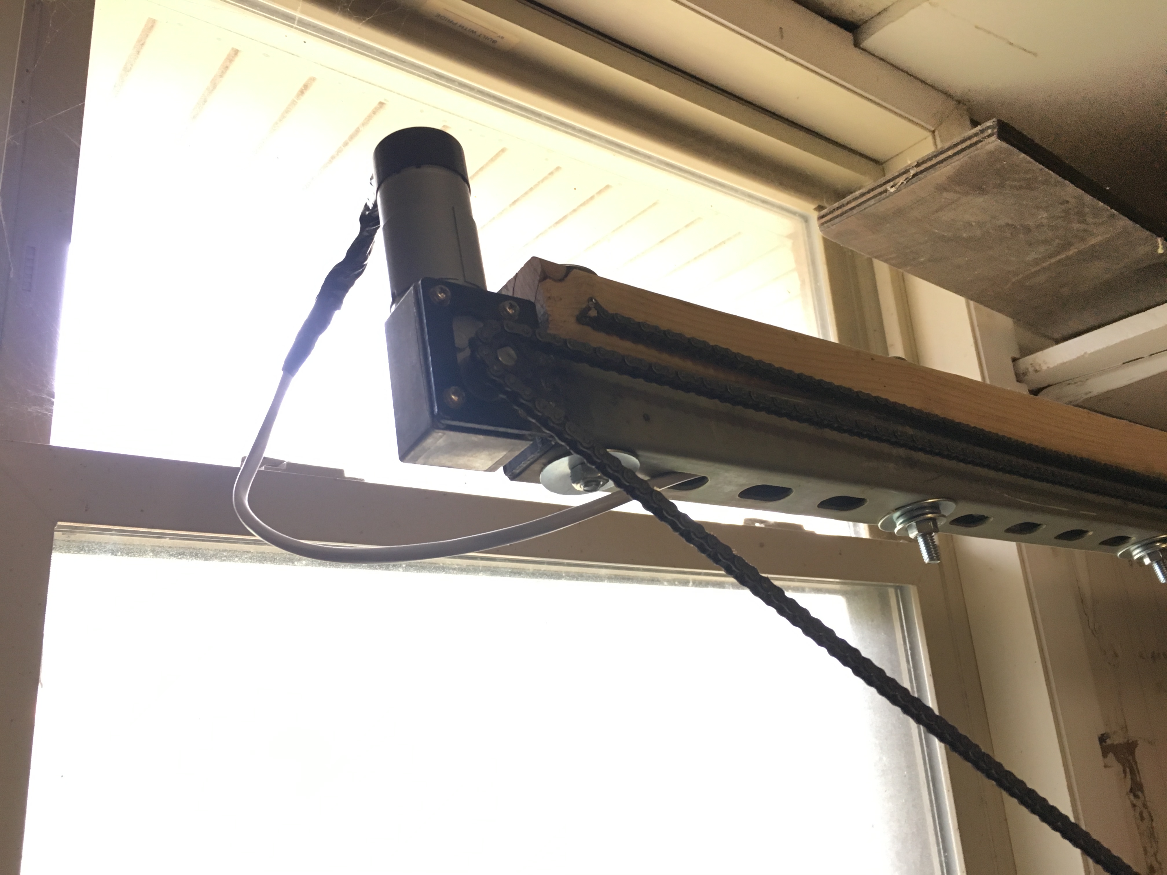
The stock motor brackets are welded to the end of the strut instead of the top. The thought is, the bracket on the end would be less susceptible to weld movement (weld cracking or fasteners loosening, if going that route) …thinking the forces on the weld would be slightly less. I meant to have them pointing down to reduce overall footprint, and aesthetics. After trying to solder the motor connector pins to the cable wires, I gave up and bought some pre-made pig tails and then soldered those to the cable. Not pretty but saved a lot of time and frustration for me. I could dig up some amazon links if anyone is interested.
.
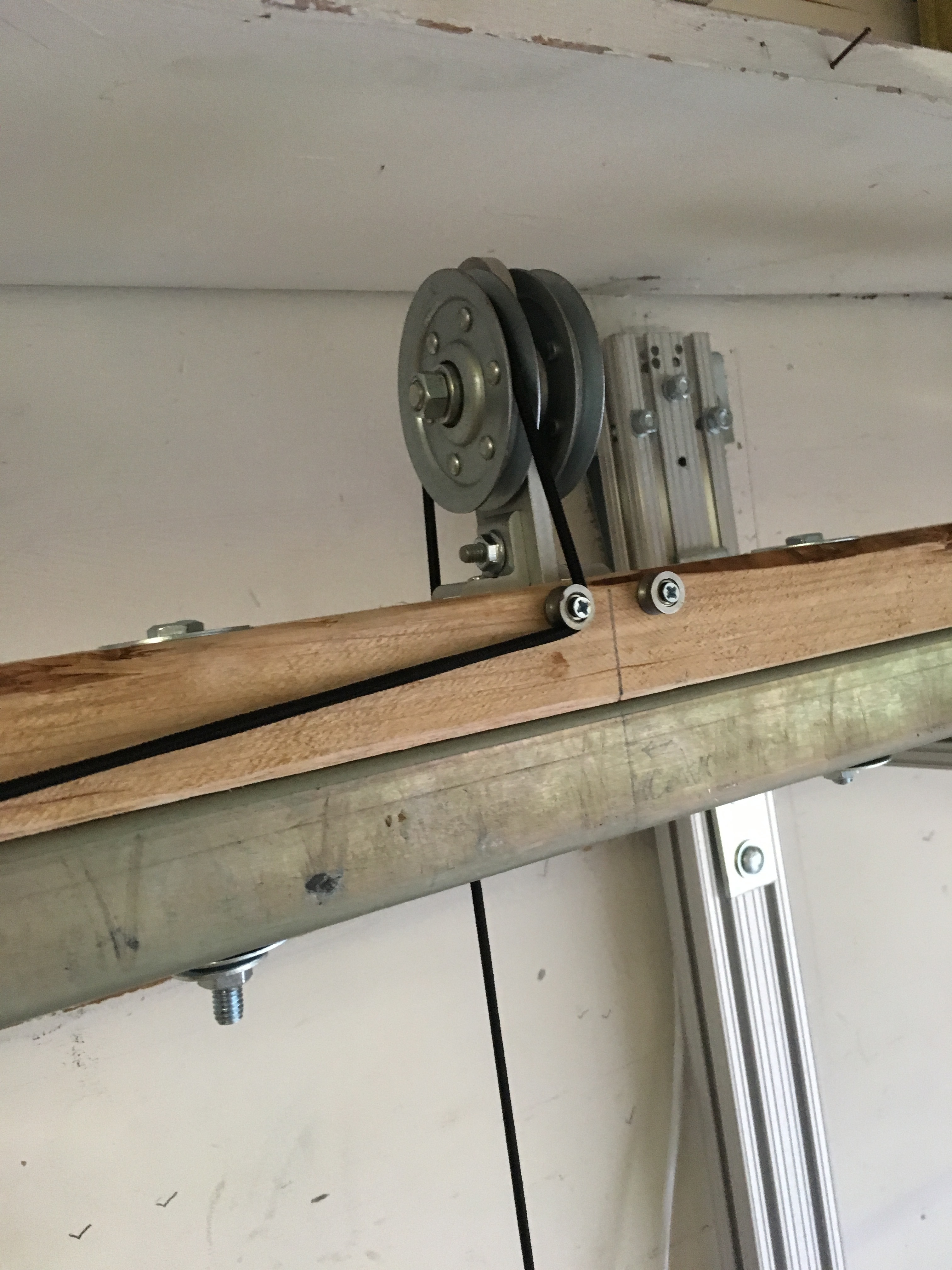
I also found this pulley at work and used it for my chain slack tension. 2 lb. concrete bricks from Home Depot seem to be working well at providing a consistent amount of force on the slack. I have moved the sled in all corners of the 4x8 and the bricks move up and down only a few feet. I moved the left side brick off to the side to prevent them from getting tangled. A downside to putting the bricks in the middle is that it can get in the way of whatever you may plan on storing back there.


.
I’m using @dlang ‘s metal pantograph linkage (link to my sled/linkage build notes) and the same 2 lb bricks with bolts drilled through. I also bought 1/8” HDPE and glued it to the bottom of the sled to reduce friction. It’s getting fairly scratched up already, although I think it glides better than wood at the moment. I covered the bolt holes from the linkage and bricks with the plastic.
I have also implemented: @geeklimit ‘s “Inexpensive fixes for z-axis slack”, as well as @ShadyG ‘s “router hat” and bought the BlueSmokeHerder TLE board.
I’m still working out calibration issues. I’ve gone through the “standard” calibration about 5 times and get varying levels of accuracy in the sweet spot. The last attempt I changed a bunch of the advanced numbers based on actual measurements (since they were so far off from software calculated numbers) and the result is not as good. I’ve been getting ready to do @Joshua 's holey calibration and should be able to implement that this weekend.
Cheers
UPDATE: May, 2019
One of my objectives was to have a collapsible frame and not cover the window or obstruct my other tool bench area toward the front of the garage. In order to stick with all that, I got a little crazy and bought a 12’ steel “s” beam from Metal Supermarket for $109. The beam is pretty rigid and does not flex with my weight on it, however, the next weakest links in my “unique” design continue to present themselves…
I drilled holes through the top and bottom of the beam to use the same mounting technique from before. This cobalt bit from HomeDepot made quick work of it and I highly recommend it!


I mounted the beam with the same hardware as before, so its position can be adjusted.

Pulling down on the unsupported beam at left results in a transfer of force to the bracket and the long 80/20 rail; both flexed. I added supports here to transfer the force back to the wall.

Now, pulling on the unsupported left side of the steel beam, the very top of the strap hinge is flexing away from the wall (these are the only anchor points). I may try to run another bold, closer to the hinge pin, into the stud but in reality the remaining flexing is not much.

Other updates will include adding a foam spoil board and a way to bump out support for the work piece, since its existing ledge is only ~1/4-3/8 wide. Also, I will be opening up the motors to inspect the gears for proper lubrication and wear.
UPDATE: July, 2019 - Motors were very well lubricated (I saw others that were not and contributed to premature failure) and added more (superlube)! I haven’t gotten around to the foam spoil board yet. Finally completed a “first pass” of calibration but need to redo it; I think I measured incorrectly.
ALSO, super excited to receive a new metal sled and upgraded z-axis kit from @Metalmaslow. I bought this for two reasons: 1) I have some doubt about the accuracy of my mounting/installation of @dlang 's pantograph linkage and metalmaslows sled is laser cut and ready to accept the linkage so I think I’ll have less potential for error on construction/installation. 2) the stock z-axis is painfully slow and frustratingly inaccurate; it was a great, quick and dirty hack, but I’m willing to pay more for something better.
