My M4 journey starts today!

My M4 arrived in the mail a couple of days ago but have only had enough time to unbox today. Very excited to go through the process!

Not sure what to do with the stickers just yet, though I’m sure my kid will have an opinion before I do…

If I remember to record, I plan to document a fair portion of the progress. If I do, I can share it here in case anyone else benefits. As I have mentioned in other posts, I am a quick study but fairly new to the CNC/CAD world.

Thanks for the clean packaging and heads-up page on top! Now, time to get started…

6 Likes

Here’s my first sit-down and takeaways from the instructions:

Don’t mind the stuff behind my computer…

So as I pulled the pieces out of the box, I noticed that one fasteners bag was ripped, and the majority of my screws and locknuts were found in a corner. Fingers crossed i didnt lose any in shipping but the box was in good shape so I’m confident I’m alright. Also, they’re the standard screw size, so not hard to replace!

The pics in the step by step are clear and show the placements of gluing very well.

First suggestion to users: when adding magnets, do each separately, then place out of reach and away from the kext one. They do stress distance between each, but even one slip when you’re super gluing can not be fun. I had a close call of making things much more difficult for myself. The magnets’ attraction is stronger than the glue (for longer than you’d expect with superglue).

Second suggestion: when assembling the belts and motors, do each step x4 instead of repeating each belt system individually. This is especially important so you don’t miss one particular prep of locking nuts that wouldn’t be caught until later in the build. Plus, easier to glue up, loctite, grease, and compare symmetry.

You will notice a butter knife on my table. I found this one had a rounded and flat heavy end for good pressure on fitting my bearings without worrying about bending them.

On to the second half of arm assembly before my next comment!

###EDIT###

The fitting of the idler shaft is worth taking time to verify it is at least as upright as possible. The full alignment of it gets sorted near the end, but it’s a lot tougher (frustrating) to correct by then.

5 Likes

Thanks for your photos! It’s really nice to see a Maslow4 in the wild.

By the way, this little “maslow4” sticker is designed to fit on the side of those “triangular” clamps that support the Z-axis rods. But it’s an advice, not instruction!

3 Likes

The second half of arm assembly:

As warned, the first arm took some time to put together. I’m sure everyone will come up with their own plan, but I will add my method in case it helps. I placed the rollers on the motor side, with the magnet facing the sensor, which has enough attraction to keep it in place so I wouldn’t mix them up if things get jostled. When holding both halves, I found it easier to be upside down and there’s enough play with the rollers for it all to fit.

My first mistake was feeding the belt the wrong direction. The pic in the instructions is cropped so I couldn’t see which was the open end. Also, since both halves are shown ‘open-faced’, there’s an inevitable twisting of the belt as you assemble. I held the motor half (with the spool) floating above the second half, lined up the belt, then grabbed both with one hand and flipped at the same time, then i knew the orientation was right when I fed it through (big side to little side :smile: )

A piece of painter’s tape to hold the belt on the spool while assembling is a good add, just remember to remove…

I held each arm over the edge of my table so I could easily line up the screws and locknuts hidden under the motor. The screws could not reach the locknut in the opposite orientation. I also held the allen key in a way to spin it quicker. It seemed to bite the thread better, like this:

As for the other screws, I used the allen key short side to fish the locknuts to slide on it, and an easy twist to plop into the frame’s screwholes. Six spots to screw in, I used the same method, but I did have to squeeze the frame for the screw to reach, as theres enough space in the thread hole for the locknut to avoid biting. In hindsight, using a pencil to push against the locknut would have been ideal.

The butter knife came in handy again to press down and help fit the belt end into the groove.

I’d say the first arm took me about the same as the other 3 to put together. 45 minutes to think and fix my thinking, then 45 for the rest, including due diligence.

Sled assembly coming soon!

1 Like

That is good feedback. We’ll try to get a better picture for that. Which way did you have it? Was it through the other half?

1 Like

With the two identical shell halves, I’ll name them motor side and bearing side. The motor side has the spool attached, the next picture has the bearing side with the belt fed through, not indicating the feed direction or showing which side had the open end of the belt. I did also get mixed up with feeding the belt through the motor side past the rollers at one point, absently thinking it had to pass through both openings simply because they existed lol. Aside from that, the pics have been a huge help!

1 Like

Well this update is happening much sooner than I expected. The sled is a breeze to put together.

For the dust cover, I found holding the sled upside down as suggested, and using my finger sliding across the bolt head underneath was enough to get the bolt connected to the nut. Not much can be appreciated like a bolt threading with no effort!

For the linear rails, I decided to spin the allen key around its stem rolling in my fingers until every bolt was equal friction. I then used the ‘long handle’ method so I could measure the tension and not hastily over-torque.

I will hopefully have time to get working on the router assembly and final connections tomorrow!

1 Like

The M4 hardware is finally built!

Another straight forward build. A couple steps took more time than I wanted, but probably my own fault.

The PCB mounting plate fits very well to the D611, however, I urge everyone following this to make sure to click in both sides along the striped grooves at the same time. I had one tab not quite get past the edge and I had to force it past that tiny edge to fit. That wouldn’t have been an issue if I waited to press until I was sure every tab was aligned.

I also felt silly because I figured a solution to the locking nuts not quite reaching the bolt when held flush…just put two in. The first will reach and bite, the second will just fall out, ready to be used for the next bolt. Oh the time i could have saved! :man_facepalming:

Also, for the uprights assembly, I found fishing my allen key through the hole and catching the locknut helped guide it in without dropping. Also, as pictured below, if you hold your index finger over top the nut and use a couple other fingers to stabilize the key, its much easier and faster to fasten them together:


The pictures showing the heatsinks attached to the PCB weren’t available when I made this. I’m assuming I’ve installed them correctly as long as i used the adhesive side to attach directly to each of the 6 chips.

When fitting the fan module, the ridges that guide the PCB and cover into the mounting bracket have a slight grip but is easily slips. Putting the bolt in the cover, lining up the PCB with the mount holes underneath, and then a slight squeeze in order to connect the nut was the best method I could think of.

For placing the motors in the correct order, another zoomed out pic that shows the cord position and maybe numbered 1-4 near each motor might be easier to understand than to compare the current pic and gif.

Just to note, by the end of the step-by-step, there are still open connections on the PCB (covered and hidden), and the motors can shift fairly easily from upright to upright without any major friction. Both of these I’m assuming are to be expected but thought I’d bring it up here to either put at ease or rectify.

Total time to install: ~4-6 hrs. If youre reading and double checking every step on your first build, probably 8 hours.

Thanks for the instructions! Next step, firmware, interface, calibration, and then playing with the new toy!

3 Likes

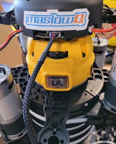
Thanks! I think I know where you are talking about for sticker location…but since I had only one I found another place that it seemed to fit nicely in the middle:

Support from you guys and the forum has been awesome!

2 Likes

You know, this is an even cooler placement! Thanks!

2 Likes