remember that the chain is naturally misaligned as you use different thicknesses of material. The motor is ~20" out from the corner of the plywood, with the chain terminating a few inches from the corner of the sled, so let’s call it 13" from the end of the chain to the sprocket, with an offset of 1/2". This is about a 2 degree angle for extra thick and thin material (assuming things are perfect with 1/2" material).
We’ve had people have their chains off of flat by multiple inches, even off by 1 inch (one hole in the bracket) this is an angle of about 6 degrees.
I can’t imagine people being off by even 5 degrees
this picture shows the angle off by 2 degrees, this looks horribly off to me, so I expect that using factory edges for the corners, people are probably going to be within a half degree
just standard construction screws, the better ones have a star drive (torx 25 commonly) and the boxes frequently include the bit. These are usually self drilling to help resist splitting.
drywall screws would work, but they are brittle
‘standard’ wood screws are a big pain to deal with (they are tapered all the way down)
a pilot hole through the first board is useful near the end.
I’m an engineer that actually likes to follow directions. Since the kit would include the screws, I’d want to make sure I’m using the appropriate screw for the test. Does this work?
I have been working on a slightly different concept in that:
It’s supposed to be a half Maslow (I intend to bring the panels already cut in half from the store).
It’s a box or sandwich construction with internal reinforcements which will make it very sturdy.
Wood sections are tall and narrow to separate front and back panels and avoid using excessive material. Panel thickness is half what would be normal to use in a one panel only construction but the same mass of material will work in a much more efficient way in terms of strength.
Openings on panels are mainly to cut some parts out of the panels (and I like the looks of it).
There are triangles in the important places in this design, it might well not need a beam. It would be interesting to measure to see if there is any deflection, easy enough to add later. The openings give many places to clamp stock. The non ply pieces look like they could be 1" stock, reducing cost and weight. It looks like the rear legs could easily be designed to fold flat for storage. I like it a lot
Do take pictures when you build it!
So I ran the tests and here’s the executive summary.
I find that both designs are incredibly strong. @bar’s design is immovable and with only three screws and without glue set up, I had to apply all the force I could to get a creak out of @dlang’s design. I think tomorrow after the glue dries, it will be immovable as well. I don’t know that glue is needed, I put all I had into it just to get the slightest of movement. There’s no way the sled will exert that much dynamic force onto the joint.
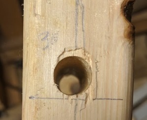
I love the idea of bolts but I could not for the life of me drill through the edge of the 2x4 and come out on center on the other side. I tried four times and the best I could do with a hand drill is to come out to the left of center on my second attempt. On all the attempts, I straddled the 2x4 with a 2x4 on each side and clamped them together to give me a solid piece to drill into (so it wouldn’t tilt). Left is attempt 2 (which is what I used for the bolt-up), right is attempt 3.
This is what I used to drill through the wood. Maybe not the best choice.
@dlang’s design went together fairly easily and I used a corner of a sheet of plywood to square make sure I was square prior to driving the screws through to the leg. The gorilla glue I used was quite tacky and I had to tap pieces in place. After the screws were driven, I checked for square again and it looked like it moved just a little, but the edges still felt good to the fingers.
Prior to screwing:
After screwing:
I drilled a perfect hole through the edge of the 2x4 using my drill press. It was actually quite pleasurable whereas, to be honest, I got frustrated with the hand drill. I think if I had bought a more expensive drill bit (a full length auger rather than a speed bore) the results might have turned out better, but I can’t say for sure.
And now I’ve got to go watch Paw Patrol with my “eldest” twin…
Maybe others can try to drill on edge and see how they do.
The ability to unbolt and respace the top beam when cutting something much thicker/thinner than normal makes me keen on the bolts, so trying to think of ways the make this hole straighter in case it does turn out to be key.
For similar jobs in the past I have had good results by marking the centre on both sides, and drilling 70% through from both sides, in this way the entry/exit points line up, and the second drilling naturally tries to take the easier path set by the first. The bolt should not have too much trouble going through, especially if using a slightly oversize bit. My instinct suggests that this should result in half the error seen when going all the way through from just one side.
The other option is to mark both sides of a scrap piece (perhaps a 2*4 in the 2 inch dimension) and keep trying until you get a reasonably accurate one, then hold or clamp that piece against the actual beam as a guide.
Using both approaches together would be even better.
to make the depth adjustable, get a 2’ length of unistrut, cut it in half.
drill through the short 2x4s in two places (drill from the top, it doesn’t matter if the holes are crooked)
use long bolts to attach the unistrut open end down to the horizontal arms. These bolts can be loosened to move things in and out.
attach the top beam to these two pieces of unistrut (short lag screws through the unistrut into the beam works for wood, simple bolts work well for a unistrut top beam)
The forces aren’t ever directly in the line between the two motors, and with @LuisP’s narrower design, are rarely going to be outside of his triangles. I could see making the top boards in the triangles go to the centerline of the frame, just to be sure. Anything more is probably overkill.