It’s a bit soggy in the UK, so i’m moving from a medium frame to a 1/4 frame for inside my shed, and a full sheet frame that can be put up outside (separate thread for that).
So, in the spirit of a recent thread, here’s my 1/4 frame (ie can cut a 1/4 sheet) - and some reasons behind the design decisions.
First - sizing. I’m pretty limited to this, it was more a case of picking the work size based on the shed size. I am using anchor points into the studs (more on that shortly), so i only had a bit of wiggle room. Playing around in the frame calculators, I went for ~2500 * 2100. It gives good cutting area for 1220 * 610 (in fact it gives a good cutting area for 1220 * 800).
Insight - if you have the freedom, don’t assume longer in one dimension is always better - if you have a limitation in one dimension (shed width in my case) - play with the other dimension when designing, to get the best width/height of the cutting area.
Second - the anchor points. Although I am doing what looks like a X-frame ala @wouldchuck’s, i’m not. It’s closer to a lot of what people do with bolts into the floor. what I actually did was brackets screwed into studs with bolts:

A few insights:
- I like this bolt-through-brackets as it lets me play with and adjust the anchor point height with 2D printed shims.
- I used a laser level to get all of these vertical. The reason being, my shed is not square, at all, and so if I want to shim but have the positions relative to each other be consistent, vertical with a laser level gives me that.
- Bolts are ok, but once you’re happy with it, it’s easy to get hold of steel rod to replace them. Use 9.5mm not 10mm. I also did a little handles on mine:

Third - the ‘frame’. I wanted something that can be packed away, so I did a variant of the X-frame:

Insights:
- They are off centre because it’s not square, so 90 degree brackets are sort of a pain. By doing it this way I just need little angled shims that are permanently screwed in.
- The anchor point bolts go down into these arms, to lock the workpiece if needed.
I didn’t take as many photos as I could, so theres a bit of skipping to the end.
I did an X-frame even though the attachment points are in the wall, because having a frame to screw things into makes a lot of stuff easier.
Insights:
- My waste board is screwed down into the X-frame - this means nothing moves round.
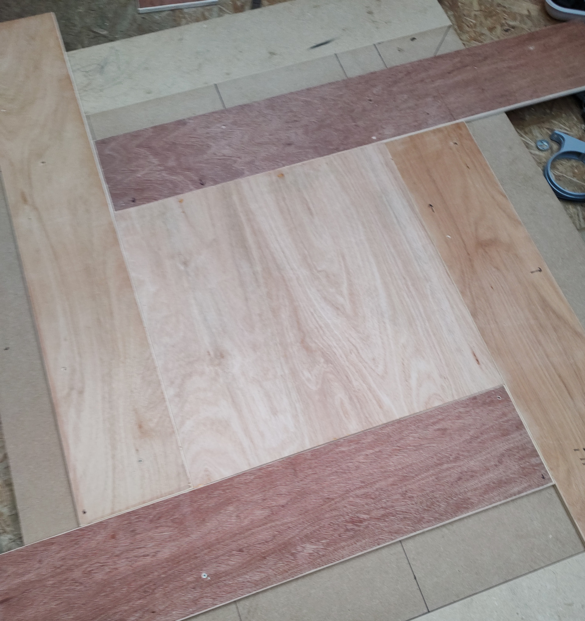
- But also, I made a while ago1200mm*200mm boards in the thicknesses I tend to cut. These have a dual purpose:
- They can be offset like this to hold any size workpiece, and screwed through to the frame.
- They let you cut right to the edge by supporting the Maslow up to it’s edges.
And that’s about it. Works well for me, is very solid, and can be put away / set up in about 10 mins if needed.
Edit (forgot the spacers)
For adjusting the anchor point height, I printed a bunch of spacers - what you see here is far more than needed:

Originally, the black ones were going to be for setting the anchor height, and red ones for quick adjustments for material height when experimenting. In the end, the red ones also were a lot of the smaller shim heights.
I printed something like 0.5,1,2,4, 6, 8, 9, 12, 18 and 40mm sizes. To get what I wanted I actually did:
- Use a long straight edge (spirit level, metal edge, etc) that is long enough to lay across the wasteboard and extend all the way to the corner to get a reading on level with the top of the wasteboard.
- Shim to this height, and repeat for each corner.
- Look up (or measure in my case of a non-standard Maslow) the height of the bottom of the lowest anchor point.
- Add shims to this value to that corner. Repeat for each corner based on their arm-heights.
- I then gathered all the shims for each corner and taped with 50mm tape wrapped round to make a single long shim trimmed to the correct height for each corner.