One of the main reasons I’ve wanted a CNC router, is so that I can build kayaks. I’ve been interested in kayak building for quite a long time, and a few years back I decided to build one. I choose the skin on frame construction method because it is very good strength to weight ratio. I cut the forms of my first one with a reciprocating saw, but I knew there had to be an easier way.
Many boat plans come as a table of offsets, basically a table of coordinates that when plotted, give you a cross section of a boat. Plot out a few cross sections, and you have forms or ribs, depending on the style of construction.
For my design, I used plans from Yostwerks.org, the Sea Tour 17 Exp.
HAB = Height Above Baseline
HB = Half Breadths (centerline to the outside edge.
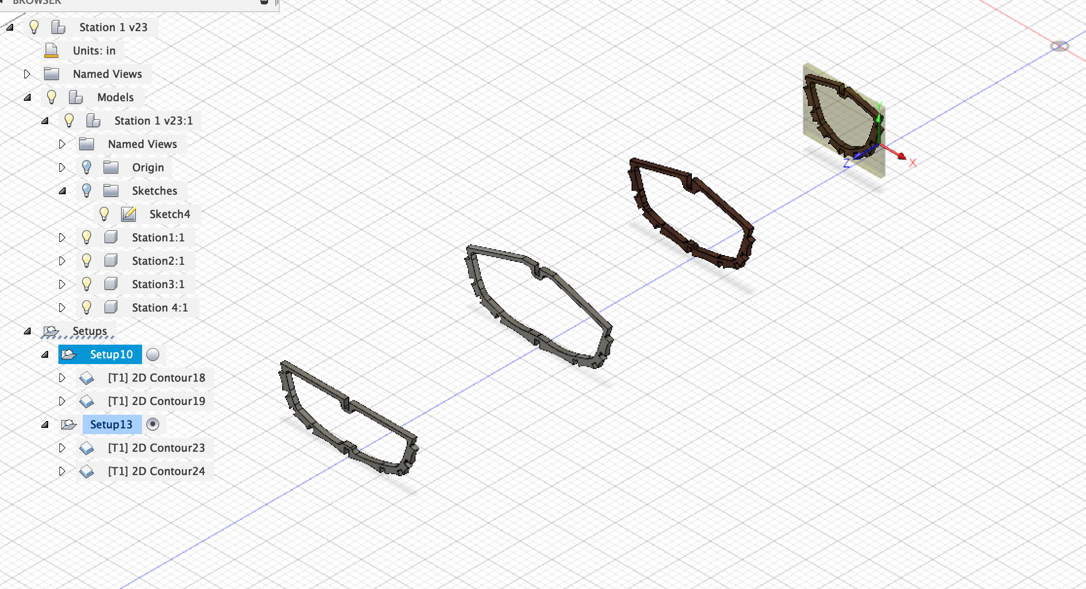
Starting one section at a time, you mark the keel at the measurement provided on the center line. For chine one, you measure out from the centerline the distance specified for HB, then up for HAB. Once you have all the coordinates plotted for one section, just connect the dots, and you have half the profile of one section. I’m drawing this up in Fusion 360.
Thats a pretty cool project. Building the items needed for you hobby is extremely fun and nerve racking. I make my own snowboards and enjoy the process a lot, not nearly as much as riding something you have made yourself though. Keep us up to date!
kayaks, rowing and sailing dinghies, and other things either in pre-cut kits or sets of plans, unfortunately not in digital form but excellent proven designs, and they run one of the baddest wood CNC mills I’ve ever seen.
I considered both cedar strip and stitch and glue when I decided to build my first boat, and they are both beautiful, but my considerations were weight and cost. Marine ply and cedar are pricey, and a skin on frame kayak uses much less of both materials, and my kayak weighs 10 to 20 lbs less than a cedar or stitch and glue kayak.
I have seen Chesapeake Light Craft boats, boats and set up though, and it’s really cool what they’re doing. I’m sure they are who inspired me to pursue the CNC route. I built my first one, hand cut, 5 years ago. I’ll be getting my Maslow in September hopefully, so my second Kayak will be done this fall.
Just a heads up Since you are using Fusion 360 there is a Slicer add-in that would work great for making Kayaks. Make a solid object and then use the slicer to create the ribs forms to lay your skin over…
Yes, my Kayak was a stitch and glue design from Devlin and I did a CAD plan for a small pram I built and use on my Trawler as a dinghy. I love the stitch and glue method and the Maslow CNC will be perfect for cutting out the profiles. One thing I’ll run into is having to find a way to “join” one or two sheets together when the required piece is over 8’ long. I’ve tried a traditional scarf joint but I need more practive CLC (Chesapeak Light Craft) and others use a puzzle joint or finger joint to glue the pieces together. I could do something on CAD, I was just wondering if there was a “shape” or “block” I could use in Qcad.
I use Qcad to create a DXF from the lofting points. I use Estlcam to convert the DXF into Gcode. Whereas I don’t have a machine yet, I did download the Ground Control and used it to import one of my stitch and glue boats into it. Seemed to work great so I’m excited to try an actual cut some day!
I finally got my Maslow put together, and have started messing with my drawing, and have made my first cut. I’m so happy with the way it’s turning out. I’ll post a bit more about my process later.
Very cool! Are the dogbones on the longitudinals/chine logs on purpose or could you just trim round corners with a chisel (or round over the logs at the intersections)?
My understanding is that you can use a gradient to create a slope for the scarf joint. Also, scarf joints are easy to make by hand if needed, especially in plywood, which creates “topo lines”.
I could round over or chisel the corners, but I don’t want to. I could also scarf the joints, but it’s not a strip or plank built boat, so I don’t really see a need. Everything is going to be lashed and glued. It won’t go anywhere.
These are just test cuts so I can have a physical representation of what I’m drawing. When I built an actual boat, it will be made from 1/2" marine grade ply. The first one I built 8 years ago weighted only 25 lbs and was hand cut. I expect to shave a bit off the weight by optimizing the design a bit.