Thank you, this has been merged. Sorry for the delay, life got in the way.
Thank you guys for all of your work! I’ve had my Maslow for over two years and I’m finally going to be able to set it up. I will be using FreeCAD most likely and this thread looks like a God send! I will also do my best to help improve as I can.
3 Likes
Great tutorial. It appears that some of the images are out of order, but that could just be me. Seems like some of the Path Tool screen shots show up early… Still, AWESOME tutorial.
However, WITH this tutorial, you answered a couple of my questions:
- With the demise of makercam.com, you’ve allowed me to find a work around: Are there alternatives to makercam.com? Yes… I CAN use FreeCad!
- When I’m generating my own g-code, what dialect do I use for my post processor? grbl… Again, thank you!
I was stuck on these two questions and was looking for a tutorial on FreeCad’s Path Tool for specific use with my Maslow.
Thanks for the help and please keep up the good work!
You can install Walt’s Maslow post-processor, as described above.
1 Like
Thanks! I’m using 0.18 on a Mac and I’m pretty sure you just saved me more than one headache.
And for those of you who are also using FreeCad on a Mac, you’ll need to do the following:
- Find the FreeCad.app on your system (most likely under applications)
- Show the Package Contents (right click)
- Navigate to the Contents/Mod/Path/PathScripts/Post folder
- Drag/Drop the maslow_post.py into that folder
You may, or may not want to re-start FreeCad. Mine seemed to work without the re-start, but Murphy is everywhere. Ignore him at your own peril. (I restarted the app anyway).
Thank you for putting this together! This walk through showed me exactly what I needed to get my first gcode out of FreeCAD. I used your post also. I have run into a problem where GC tells me that the sled isn’t keeping up with the expected position. Is this affected by having the Z axis moves on the same line as the XY moves? Thank you again for your work!
EDIT: I did a quick search for corrections and tried changing the Advanced Settings but then I saw that my slack chain isn’t performing the way I want it to so I grabbed some pulleys and I will be installing those soon. I got it to start cutting and 30mm/s was way too slow with a 1/8” 2 flute router at 10K rpm. Changed it to your recommended 42mm/s
1 Like
Are you sure you’re asking for 42mm/s?
I realized that this was all messed up last night, I just haven’t edited my post because you are absolutely correct. I manually changed the G-code to 800mm/min and that seems to work well with my spindle. I should have read through more of the posts to catch that I was missing some information. Thank you for pointing that out!
I am having trouble with the “path pocket”. I clicked the button that seems to be correct but I have different selections then shown on screenshot:

Edit: I was looking at wrong screenshot. Noticed the 2nd photo isn’t selectable so when I hit the next arrow from first one, it skipped ahead 3 screenshots to the next selectable one. Unfortunately I’m still stuck as the second screenshot is too small for me to read

Archie,
When making this tutorial, I just left the defaults in the options you have indicated.
However, I was working on a new piece over the weekend and noticed that in the newest version of FreeCAD, I’m having issues with Path Pocket. I’m using 3D Path Pocket now. The button is on the far right of the Create Path toolbar, or you can go to the Path menu then select 3D Pocket and try that. If you’re still having issues, try using a smaller diameter router bit in the tool setup. If the tool diameter is wider than the path it is trying to make, it won’t make the path.
Let me know if that helps!
~Walt
Thanks Walt, I’ll give it a try when I get home.
Edit from home: Used “3D Path Pocket” and it seems to be working

1 Like
What is next step once we generate tool paths? Not sure how to get it from this to being cut out by maslow
Once you export the GCode, you can use the Maslow Ground Control to cut it out on the maslow.
Thanks again! Forget about exporting. Pretty sure I just saved  but I’ll give that a try tomorrow.
1 Like
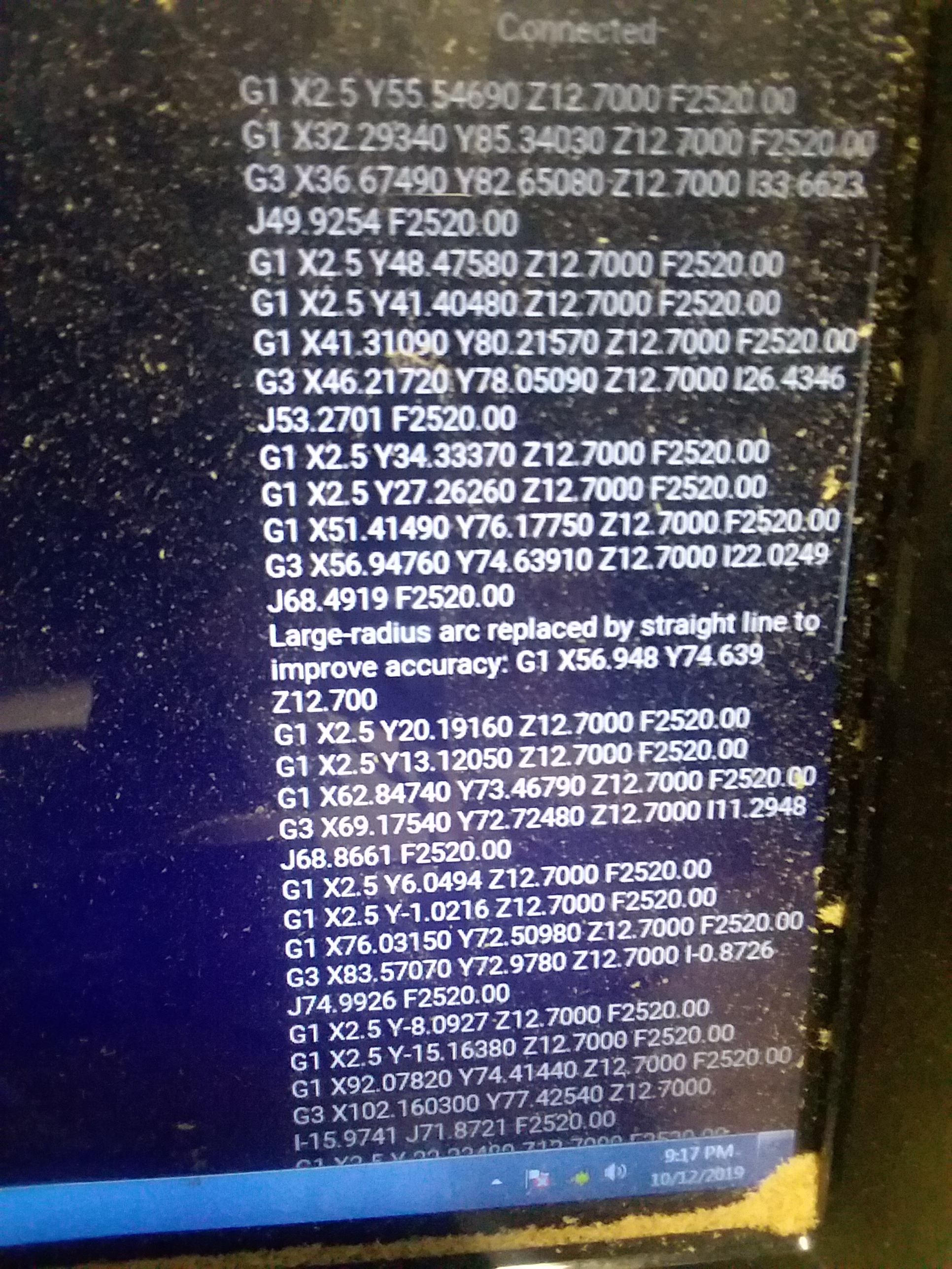
Was able to create gcode and run project but Ground Control changed a curved line to straight one for “improved accuracy”. My best guess is it did this because the details were too small for my 1/4" bit but not really sure.
Yeah, it says that a lot on the Maslow M when you’re cutting it as well, and that’s not overly straight in any direction but it cuts well lol I wouldn’t be worried about it, personally.
I have a 1/8" detail bit that I use for engraving. I sometimes have to lie to FreeCAD and tell it the bit is smaller to get it to plot the paths correctly. The letters or designs look slightly thicker when I cut them out on the Maslow, but it doesn’t leave out the narrow bits.
1 Like
Lol nice trick. I posted to FreeCad forums as well and it seems the pocket issues were caused by my use of b-spline to create the curve. Changed sketch to two half-circle arcs and path pocket worked just like your demo. 
it’s not uncommon for CAM to require a little clearance between the bit and the
next line to be cut (not allowing you to go exactly the width of the bit), how
much clearance is usually configurable if you dig deep enough.
David Lang
Hi there.
First of all, thanks so much for putting this together. This guide saved my bacon while setting up my Maslow.
Also, chrisb over at the FreeCAD forums had these suggestions that he thought might be helpful:
May I kindly suggest some corrections and improvements?
Issues:
- The sketch is created outside of a body adding unnecessary work
- The sketch is not constrained (not really a problem only an issue)
- In Step 6 you create already a body before even having a solid
I suggest:
Step 2: Open PartDesign workbench and create a new sketch. (This creates an enclosing body.)
Step 3: choose XY plane as before, but it will look different
Step 4: I would recommend to add dimensions for, lets say an 8mm bit
Step 6: move the images to the job creation step.
3 Likes