if the bottom tensioning has any effect on where the router is, it’s
significant.
what is the formula for figuring this out?
motorized bottom tension can be calculated, but the stretchy cord is not going
to be that consistant, so I don’t know that you can calculate it’s effect.
That’s the challenge. It basically is a variable length spring with a force vector dependent upon how much chain has been extended by both motors. The math can’t be trivial.
If I did the math right, you can get more force to the left side when the sled is over to the left side and vice versa. However, the problem appears that the downward force when the sled is at the top corner is about 3 times the horizontal force when the sled is in the bottom corner. So if you think you need “5 lbs” of horizontal tension in the bottom corner, you will be effectively adding 15 lbs of weight to the sled when its in the top corner.
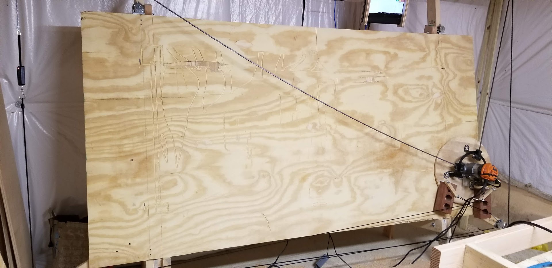
I used excel charting the best I could… this is an image of the left half of the plywood.
Thanks again @dlang for your clarification and guidance! We did the following:
Added three coats of paste wax to our new wood Maslow sled (old sled had some)
Flipped cotter pin around as sometimes it catches and lose 1/2 inch. Moved screws out to make sure bearing guide on ring kit can go all the way over, gained 1/8 inch.
Two cuts near corner at 35 ipm actually finished without complete failure - although a bit wobbly. (Top right missing corner would have been fine, bad estimate of where to start)
Third cut near corner at 5 ipm actually came out perfect Maybe next test will be 10, dunno.
So we can now cut small items in corner areas as long as we program/CAD in Easel or Makercam to go slow.
I had an idea which might be valuable. Change the setup such that there is a vertical stretchy piece (purple) that connects to non-stretchy (red) rope that connects back through the pulley. This is shown in the attached figure, a hack of your original. Because the rope is not stretchy, the horizontal vs. vertical component of the force from the non-stretchy rope doesn’t matter. The vertical length of stretchy rope is what produces the vertical force, and it is always downward.
That is a good point. If the motion of the red chain is greater than the motion of the sled, this will be accomplished. If the sled moves to the left, the intersection of the three ropes will move to the left faster. This will result in the stretchy rope being angled slightly to the right (up and to the right), and there would be force pulling the sled to the left.
the force would not be down, it would depend on the tension of the two legs of the red stretchy, if the piece to the right is being stretched more, it will pull to the right and the blue (not very stretchy) rope will be angled, not vertical.
I had an idea with this, I was trying to figure out a way to use the existing movement of the chains to apply tension how its needed. My MS Paint skills are not as good as the others here, but here is a very crude picture of what i was thinking. If we wrap the chains over the top of the motors so it hangs down, then attach some elastic cord to the end of that chain, that goes around 2 pulleys first below the motor then to the opposite side of the frame, then back to the opposite corner of the sled. When the sled moves to the bottom right, there would be the most pull on the cord. same for the other ‘axis’ Maybe use some pulleys to multiply the force somehow?
Yep, this is very similar to the first post on this thread. I tried your version of the configuration as well – when the sled is in the bottom right corner for instance, the orange cable has to stretch further than the chain has let out, meaning you get a bit more force on the orange cable than what you gain with the red cable’s retraction. If the force from the orange cable was co-linear to the opposing chain, you’d be good to go, but the orange cable ends up lifting the sled upwards and to the right because of the position of the opposing chain in the corner, so it makes the system less stable.
I’m not saying I did everything right, or that you shouldn’t challenge what I found, just that my data pointed to issues with this particular approach.
For comparison, the original approach (First Post), [when in the bottom right corner] applied 5.1 lbs in the wrong direction, and 6.6lbs (Max) in the correct direction. The one pound of force in the correct direction was not worth all of the unpredictability it introduced into other aspects of the system.
Wow, you did your homework! It did seem like a very simple approach, so was surprised wasn’t mentioned. What about doing a slight alteration using a pulley or however many is needed. Using pullies you can multiply distance. Really hard to explain this. So basically all the while the sled is on the left side of the board the length of the slack chain over the left sprocket is always going to be longer than the right i think. so if we can use a pulley or two to multiply that going into an elastic cord, then we should be able to apply more tension on the right corner of the bottom of the sled. I am assuming so long as the tension to the bototm left of the sled is greater then the bottom right when the sled is on the left side of the work area would produce better results.
Hard to explain but Bad paint incoming! so black is chain / non-elastic, and colours are elastic. I think this setup would double the tension in the right direction and half it in the wrong?
Now you’re EXACTLY describing what the original post was doing! Go check out the very top of the forum and you’ll see what I mean – Glad to know someone else came to the same approach as me
EDIT: I’ll save you the scrolling:
I did triple multiplication, because double didn’t end up being enough.
EDIT 2: I do see one difference which is that my chains were pulley reduced so that I didn’t have to have them make the corner around a pulley. That makes the reduction closer to 1:2 (similar to your drawing above).
Ah, so it does work, that’s what i got from your original post? and as for the chain being reduced as well, that was more too much to draw out in paint then the way I was thinking in my head. If i could source some elastic cord locally i think i would try this myself, but being in Regina Saskatchewan, really not a lot around here. Even being the ‘capital’ were just over 200k.
Sadly, it does not work, no. The theoretical implementation (when not in operation) showed the mechanism behaved as intended. However, the mathematical models that calculate chain sag are based on specific static forces that are impossible to predict because of the way that elastic cord behaves in a complex system. Because of this, the best solutions so far have suggested increased sled weight, reduced sled friction, and increased top-bar length (distance between motors). <-- none are perfect solutions and all three have drawbacks, but they are simple, inexpensive to implement, and easier to program for. The program’s ability to understand the real-world physics of the system’s behavior when in operation is currently just as important or more important than the mechanical aspects of the existing system.
instead of using elastic rope which has unpredictable tension, maybe constant force springs would work better? I have never used them, but I bought some for a project and they have relatively constant force over their pull distances. Please note I have not read the entire post so I may have missed something. send me a pm and I can mail you some.
Frame is made mostly from wood, that comes in a kit
But the similarities end there as it is more of a traditional gantry CNC X, Y table and uses a constant force spring to counteract the force of gravity on the Z axis and spindle. It’s also over 10x the cost of the Maslow kit.
Don’t immediately dismiss this idea because it’s impractical. I’m trying to take the conversation in a different direction. I’ve got the start of an idea, I want to see if anyone can make something of this concept. Use the idea but move the pieces around to make it practical.
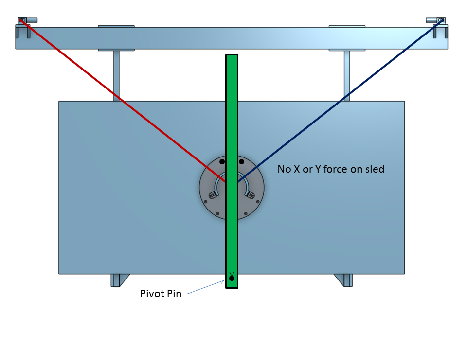
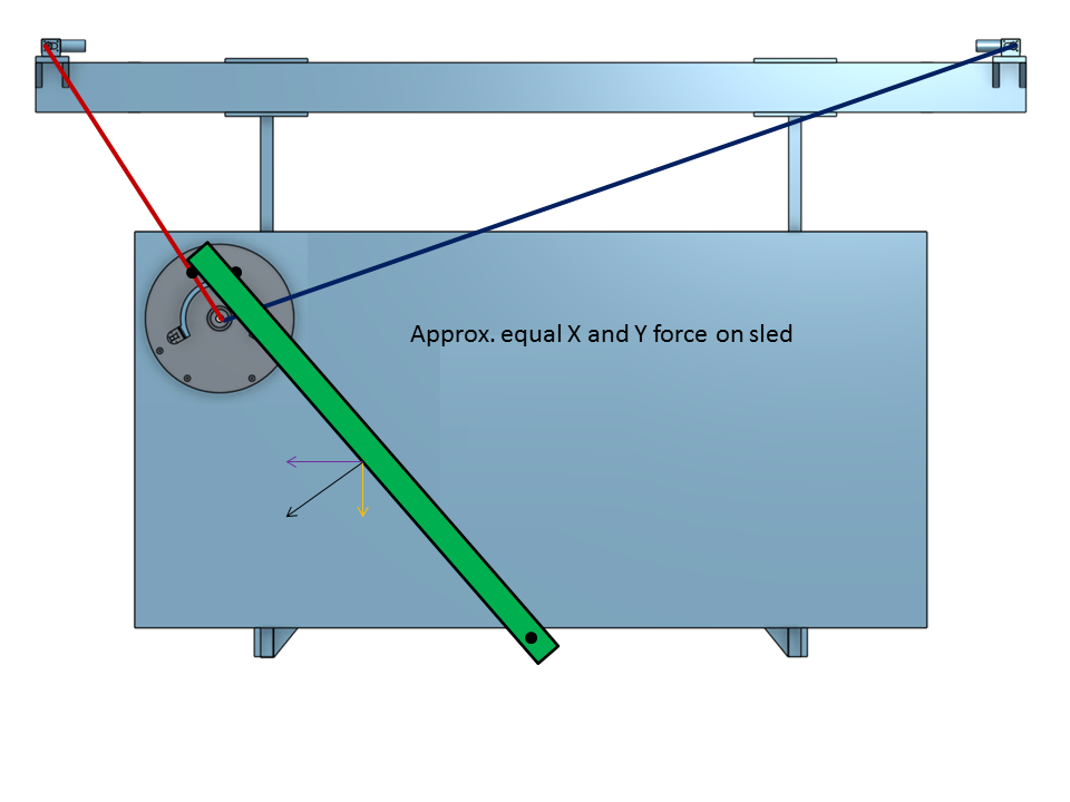
What we need is something that acts like a magnet or gravity on both right and left side of the Maslow. Something that pulls more as the sled gets closer and pulls less as the sled moves away. The opposite of a spring. I’m thinking about using gravity itself. Using a board that rotates about pinned joint and connects to the router sled with some rollers (or similar). As the sled moves away from the center line, the board creates a moment about the pivot pin and applies force to the sled.
On the center line the board is balanced. The resultant force on the sled is 0 because it’s all resting on the pin.
This design obviously wouldn’t be practical as-is. If it could be relocated to hang off the chains somehow on the backside, and we could flip X and Y components at the bottom left, then we might have something to work with. Any thoughts?
I think a more practical solution would be a lower beam with additional 2 motors. Chains would then pull on 4 sides of the sled.
However, this would mean an additional board too and adapting the software too.

 Maybe next test will be 10, dunno.


 If i could source some elastic cord locally i think i would try this myself, but being in Regina Saskatchewan, really not a lot around here. Even being the ‘capital’ were just over 200k.