Thoughts on the next iteration of the Maslow 4

John Wolter wrote:

What I don’t get in all this discussion is the assumption that the spools need
to rotate to align with the anchors. In the original Maslow there were only
two motors and hence two measurements to get us two unknowns, x and y. There,
it was critical that the chains point at the center of the sled because
otherwise you needed a third variable which you couldn’t measure.

On the Maslow 4 you have 8 measurements at your disposal (4 encoders, 4 motor
currents) if you had fixed arms, you basically would have three unknowns, x,
y, and rotation angle. The math to calculate those is a little hairier, but
not a lot hairier.

What am I missing?

We are thinking that the math is enough hairier that we don’t know what it is,
especially when trying to do auto-calibration.

It may be that the key issue is knowing the anchor points rather than trying to
calculate them.

With the Maslow 1, the initial code thought it accounted for the rotation, and
it did a pretty good job with Bar’s prototype, but when it got out in the real
world with other people building the machine, there was just enough variation
that the results were really bad (problems in measuring accurately over the long
distances between anchors being a large part of it)

If you can show the calculations for both forward and reverse kinematics (i.e.
“here are the x/y coordinates, what should the belt lengths be” and “here are
the belt lengths, what are the x/y coordinates”) where you either account for
rotation that happens, or eliminate the rotation, we can see about adding that
in the firmware as an option

The cubiio seems to solve this according to their videos, we don’t know how. I
hadn’t heard of them until a week or so ago. they apparently shipped their
devices in December and it doesn’t look like there is much in the way of updates
since they shipped everything (and I don’t see any links to a community)

David Lang

Actually, reading this diagram a bit more, it looks like we’d just have to get the distances between each belt measurement point, where they come out of the spools on the maslow, and then use half the x/y distances between those 4 and insert those values in the relevant parenthesis for each calc.

For example:
D1 = sqrt( sq( Xoffset + x - 0.5( sledX ) ) + sq( YMS - Yoffset - Y + 0.5( sledY ) ) + sq( Zoffset ) )

Where sledX and sledY are the distances between the ‘start’ points of each belt on the sled on the X and Y axes, respectively.

I would expect that, if it’s a good calc to get the right belt lengths to put the center of the unit at the desired XY, it should also have each of the belts at their minimum length to achieve that and maintain orientation. From watching the Maslow 4, it appears that it is only rotating because it is both free to do so and because of friction between the sled and workpiece.

looking at the instructables, that is using a ring so that the lines are always
pointed directly at the bit. So I don’t see anything there that handles the
anchors on the sled being fixed and off-center.

the rotation is only just torque and friction on the maslow because the arms can
rotate. When they are attached to a fixed point on the sled, the math gets much
messier because the tension on each belt isn’t going to be the same.

when you are in the right center edge of the workpiece, you have a lot more
vertical force going to the top right anchor than you do going to the top left
anchor. the bottom right belt won’t help as the sled rotation will tend to give
it slack, it would then be up to the bottom left belt to be applying enough
force to the sled to prevent rotation.

it doesn’t help that the belts are going to stretch a bit, providing the ability
to rotate even with all the lengths theoretically fixing it in place.

But it’s also possible that I’m just oo gun-shy from the earlier maslow and it
is simpler than I think.

David Lang

Yes. It is using a ring and effectively already works just like the Maslow.

In my last response, I took the equation for the relationship for the length of one of the belts and the XY coordinate of the center of the carriage and added in an additional transform that, at least geometrically, should compensate for the belt not drawing that line through carriage-center anymore.

As far as I can tell, we shouldn’t be concerned with the angle of the belt, but rather the length, and that doing that for all 4, with anchors and points for the belt measurement locations on the carriage known, should produce the same behavior we are seeing with the Cubiio.

For instance, I’m pretty sure Hangprinter’s carriage system would be able to handle a 2d plane just fine with a similar sled as the maslow, and it also doesn’t have the lines tracing vectors through carriage center.

With multiple examples out there, it just seems like a geometry problem and just providing XY offsets from carriage center for each belt’s “attachment” (measurement) point on the carriage.

1 Like

I realized I could use the sketch function in Ondsel/FreeCAD to prove that belt lengths being correct should inherently keep orientation correct.

I have constraints to keep the carriage 100x100 square and to keep that datum in its center. I have parameters for setting the XY offset of the center datum from 0,0 (bottom left of large rectangle). The rectangle is locked in place, and the lines for each belt have their endpoints locked to their respective corners of each shape.

No matter what I set the center point to, this math updates the constraints (length) on each “belt” automatically and keeps the carriage oriented square with the frame.

The carriage is not constrained to prevent rotation. If I remove the calculated restraints on the belts, moving the centerpoint immediately rotates the carriage.

So, in relation to the diagram from the plotter example I shared previously, this is the math for each belt:

D1
sqrt((xOffset + carriageCenterX - sledWidth) ^ 2 + (YMS - yOffset - carriageCenterY - sledHeight) ^ 2 + zOffset ^ 2)

D2
sqrt((XMS - xOffset - carriageCenterX - sledWidth) ^ 2 + (YMS - yOffset - carriageCenterY - sledHeight) ^ 2 + zOffset ^ 2)

D3
sqrt((xOffset + carriageCenterX - sledWidth) ^ 2 + (yOffset + carriageCenterY - sledHeight) ^ 2 + zOffset ^ 2)

D4
sqrt((XMS - xOffset - carriageCenterX - sledWidth) ^ 2 + (yOffset + carriageCenterY - sledHeight) ^ 2 + zOffset ^ 2)

x/y/zOffset values can be assumed to be 0
sledHeight/Width values are the offsets from carriage center to each belt measurement location, in this example they are half the true height/width of the carriage, respectively

Someone capable of testing their own firmware forks could probably implement test this on an otherwise-unmodified maslow 4 if they locked their spools at 45 degree angles.

2 Likes

now make the belts just a little too long (say 2mm too long), due to belt stretch. how badly does it hurt the positioning of a 'points at the center) setup vs the ‘fixed offset’ setup?

I also don’t see any way to do reverse kinematics (go from belt lengths and an unknown angle to position, something that would be needed to try and do calibration.

1 Like

Testing this in VS Code tells me that I have potentially found a solution. This will have been my first time cobbling together python, most of my experience is logic circuits, JS/C#, and various node-graph “languages”, so bear with me.

Note: I’ve removed the x/y/z offset values to simplify the code, since this should work both with or without them. This example assumes bottom left corner of frame is 0,0 and that the belts are parallel to the plane of the work surface.

from scipy.optimize import fsolve
import numpy as np

# Define constants
sledWidth = 100.0  
sledHeight = 100.0  
XMS = 800.0  
YMS = 600.0  
L1 = 430.116  
L2 = 430.116  
L3 = 430.116  
L4 = 430.116  


# Define the equations
def equations(vars):
    carriageCenterX, carriageCenterY = vars
    eq1 = (carriageCenterX - 0.5 * sledWidth)**2 + (YMS - carriageCenterY - 0.5 * sledHeight)**2 - L1**2
    eq2 = (XMS - carriageCenterX - 0.5 * sledWidth)**2 + (YMS - carriageCenterY - 0.5 *sledHeight)**2 - L2**2
    return [eq1, eq2]

# Initial guess for the solution
initial_guess = [0.0, 0.0]  

# Solving the system of equations
solution = fsolve(equations, initial_guess)
carriageCenterX, carriageCenterY = solution
print(f"Carriage Center X: {carriageCenterX}")
print(f"Carriage Center Y: {carriageCenterY}")

# Define the equations
def equations(vars):
    carriageCenterX, carriageCenterY = vars
    eq3 = (carriageCenterX - 0.5 * sledWidth)**2 + (carriageCenterY - 0.5 * sledHeight)**2 - L3**2
    eq4 = (XMS - carriageCenterX - 0.5 * sledWidth)**2 + (carriageCenterY - 0.5 * sledHeight)**2 - L4**2
    return [eq3, eq4]

# Initial guess for the solution
initial_guess = [0.0, 0.0]  

# Solving the system of equations
solution = fsolve(equations, initial_guess)
carriageCenterX, carriageCenterY = solution
print(f"Carriage Center X: {carriageCenterX}")
print(f"Carriage Center Y: {carriageCenterY}")

From what I can tell, we should be able to use 2 opposing belts to get a guess, and then the other 2 belts to get another, and then reconcile the results.

The output I got from the above is:

Carriage Center X: 400.0
Carriage Center Y: 300.00045308840976
Carriage Center X: 400.0
Carriage Center Y: 299.9995469115895

Carriage Center Y should be 300, so I think we can call that a success.

I’m not asserting that this is everything we’d need, because I don’t know that it can be applied for the Maslow, but it’s at least not a “hard” problem where there are no known paths forward for the math.

1 Like

I would definitely ditch the magnetic encoders as they are honestly are turning into a real nightmare to deal with. I can understand why after 3.5 months the “Exceeds 15mm Error” still hasn’t been resolved or even fully understood yet. I’m basically just dead in the water, as are many others because of it. Honestly, other than telling the machine to just ignore the encoders altogether and just have it run blindly on math alone (is there a way to do this?), I don’t think the problem can be fully resolved in software alone.

I understand the thinking behind using them, they are relatively cheap, simple and (physically) robust but at least the way they are now, judging by the forum post on the 15mm error, they are just too sensitive and it seems that far too many things can potentially interfere with them and effect their readings: Static build up on various parts of the machine, EM interference from the router’s motor, EM interference from the arm motors, EM interference and static fields generated from dust collection systems, magnetic interference from large nearby metal objects (there is even long thin strips steal in the belts themselves that likely generating eddy currents as they retract in and out of the machine and act like large variable antennas). Even the Earth’s magnetic field, solar weather and static build up between the air and ground can affect these things.

In future versions I would would (strongly) recommend going with an optical encoder of some kind. As (as long as they are sealed from dust and external light) they are completely immune to interference. Really, this is needed now as an upgrade for the machines we already have have.

I also think using Ethernet cables was not the best plan ethier. To transmit something as basic as encoder values (basically one serial channel) it’s kind of overkill. Ethernet cables are also really designed more for relatively clean, static (as in not moving) environments (like the back of a PC or in a server room) as opposed to the dirty, dynamic and noisy environment that is the M4. Audio cables might have been a better option They are very robust being used in harsh/dynamic environments for decades (rock concerts can get crazy), can transmit digital and analog signals as well as low power, because the jacks themselves are round, it’s very easy to design a screw on cap with a gasket to keep dust and moisture out and hold the connections firmly in place.

Zach Crawford wrote:

I would definitely ditch the magnetic encoders as they are honestly are
turning into a real nightmare to deal with. I can understand why after 3.5
months the “Exceeds 15mm Error” still hasn’t been resolved or even fully
understood yet. I’m basically just dead in the water, as are many others
because of it. Honestly, other than telling the machine to just ignore the
encoders altogether and just have it run blindly on math alone (is there a way
to do this?), I don’t think the problem can be fully resolved in software
alone.

There is not a way to run blindly, you would have absolutly no idea how far the
belts have moved

I understand the thinking behind using them, they are relatively cheap,
simple and (physically) robust but at least the way they are now, judging by
the forum post on the 15mm error, they are just too sensitive and it seems
that far too many things can potentially interfere with them and effect their
readings: Static build up on various parts of the machine, EM interference
from the router’s motor, EM interference from the arm motors, EM interference
and static fields generated from dust collection systems, magnetic
interference from large nearby metal objects (there is even long thin strips
steal in the belts themselves that likely generating eddy currents as they
retract in and out of the machine and act like large variable antennas). Even
the Earth’s magnetic field, solar weather and static build up between the air
and ground can affect these things.

In future versions I would would (strongly) recommend going with an optical
encoder of some kind. As (as long as they are sealed from dust and external
light) they are completely immune to interference. Really, this is needed now
as an upgrade for the machines we already have have.

The problem isn’t in the encoder (other than the one pin not grounded that
should have been), the problem appears to be in the communication between the
encoders and the main board. the type of encoder won’t change that.

I also think using Ethernet cables was not the best plan ethier.

I agree, I am guilty of making that suggestion (easy availability of cables in
different lengths, and I thought they would also pass the motor power). But I
wasn’t aware enough of the problems with vibration and dust.

To transmit
something as basic as encoder values (basically one serial channel) it’s kind
of overkill. Ethernet cables are also really designed more for relatively
clean, static (as in not moving) environments (like the back of a PC or in a
server room) as opposed to the dirty, dynamic and noisy environment that is
the M4. Audio cables might have been a better option They are very robust
being used in harsh/dynamic environments for decades (rock concerts can get
crazy), can transmit digital and analog signals as well as low power, because
the jacks themselves are round, it’s very easy to design a screw on cap with a
gasket to keep dust and moisture out and hold the connections firmly in place.

FAR more expensive, heavier and longer. I don’t see that as a resonable option
(and I believe that you need 4 pins, so XLR connectors won’t work) and you still
need to deal with the interference problems. They also take a lot more force to
insert/remove

David Lang

Not always easy to control all the constraints before suficient scale implementation…
I am not a specialist and may be very naive.
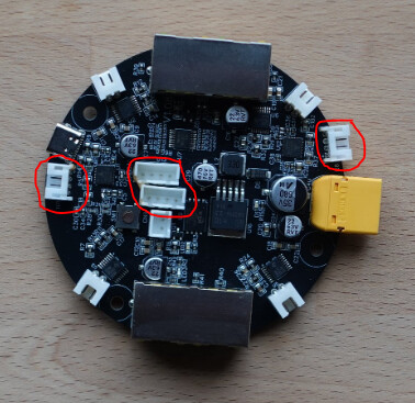
Why not using basic plugs, already used on the controller board (JST connector ?):

image

Cables could be similar whith the Z stepper motors.

Also, the cables could be soldered to the encoder board, to remove 1 interface.

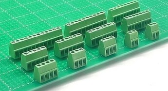
Or if we need stronger interface, we could use “PCB screw terminal block connectors” for example. With or without plug.


3 Likes

And may be tried on existing units, the following DIY solution:

Again, please don’t try my naive ideas on your maslow, unless it is confirmed by suitable people.
(I don’t even own myself a Maslow 4 (M2 owner))

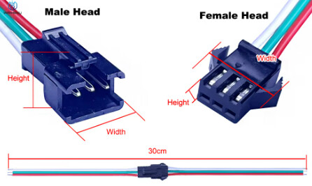
Remove the ethernet female connectors from the boards (desoldering) and directly soldering new wires on the controller and encoder doards. A simple connector solution can be chosen in the middle to allow mounting/dismounting.
(I guess basic connector in the middle of the cable will be less subject to problem with vibration?)

But we will need wiring instructions (which terminal on controller board goes with which terminal on encoder board).

image
image

https://www.aliexpress.com/item/1005006898618054.html

2 Likes

Don’t feel bad! Every great idea comes with its own set of complications. Availability and cost are pretty big concerns with a project like this. I actually think the use of Ethernet cables is really inspired; I certainly wouldn’t have thought to use them there.

1 Like

This is 100% the solution that we’re working on right now. The tricky part is finding a manufacture who will make the cables. It’s tricky to find the right combination of quality shielded cable and them being willing to make them at low enough quantity that it is possible for us.

It also just takes a long time to contact the factories, order samples, and test them to make sure they fix the issue. We’re working on it as fast as we can!

3 Likes

There is not a way to run blindly, you would have absolutely no idea how far the belts have moved.

Most lower end 3d printers essentially run blind. They do use endstops to find a predetermined “home” but after that they have no feedback for were they actually are the just “assume” that when they send so many pulses to a stepper motor, the motor moves that many steps therefore the nozzle “must” have moved so far along the axis that the motor was driving. It actually has no idea if it really moved that far or not. For the M4, it knows when all the belts are retracted since the board detects an increase in the power draw when they can’t be retracted further (so I’m guessing it doesn’t need to rely on the encoders for this). So if it started with the belts retracted, it could just count the number of pulses (and the state of the H-bridge) and just “assume” how much belt it’s let out. You would have to know the location of your anchor points fairly precisely (so the M4 knows the angle of its belts at any length). It’s certainly far from ideal but it is possible.

The problem isn’t in the encoder (other than the one pin not grounded that
should have been), the problem appears to be in the communication between the
encoders and the main board. the type of encoder won’t change that.

Oh alright, well I’m glad it has been narrowed down to communication between the encoder and the main board anyway.

I agree, I am guilty of making that suggestion (easy availability of cables in
different lengths, and I thought they would also pass the motor power). But I
wasn’t aware enough of the problems with vibration and dust.

Don’t feel too guilty, it was a good idea in theory and I mean I suggested basically a headphone jack cable, thinking the encoder only needed one or two channels (kind of like a serial pin on an arduino), I didn’t even consider power delivery so your idea of using ethernet cables at least has my idea (that even had the benefit of hindsight) beat.

I like Juju’s idea of using similar connectors to the ones are already used for the motors. But I’m legally blind and have no soldering skills (I’ve tried soldering a few times but it has never ended well lol). So hopefully Bar can come out with new boards and encoders that use a different, more robust connection type. I would definitely buy them (once my savings recovers from buy the M4 anyway).

Zach Crawford wrote:

There is not a way to run blindly, you would have absolutely no idea how far the belts have moved.

Most lower end 3d printers essentially run blind. They do use endstops to find
a predetermined “home” but after that they have no feedback for were they
actually are the just “assume” that when they send so many pulses to a stepper
motor, the motor moves that many steps therefore the nozzle “must” have moved
so far along the axis that the motor was driving.

That is correct, but the maslow doesn’t use stepper motors for the belts, it
uses DC motors. We can apply voltage to them, but have no idea how fast they
move without feedback.

I agree, I am guilty of making that suggestion (easy availability of cables in
different lengths, and I thought they would also pass the motor power). But I
wasn¢t aware enough of the problems with vibration and dust.

Don’t feel too guilty, it was a good idea in theory and I mean I suggested
basically a headphone jack cable, thinking the encoder only needed one or two
channels (kind of like a serial pin on an arduino), I didn’t even consider
power delivery so your idea of using ethernet cables at least has my idea
(that even had the benefit of hindsight) beat.

It was a nice idea and made it really easy to get cables (and get replacements
when they break, any wire that’s flexed enough WILL break eventually) and for a
lot of people, a little hot glue seems to solve the problems.

I think the hot glue solves the vibration/dust problem, but doesn’t solve the
interference problem. That’s much harder to deal with after the fact.

David Lang

2 Likes

Bar wrote:

This is 100% the solution that we’re working on right now. The tricky part is finding a manufacture who will make the cables. It’s tricky to find the right combination of quality shielded cable and them being willing to make them at low enough quantity that it is possible for us.

It also just takes a long time to contact the factories, order samples, and test them to make sure they fix the issue. We’re working on it as fast as we can!

I don’t know if this is just a connector modification or a board tweak. If this
is a board tweak, please consider having the motor plug into the encoder and
having just the one cable from the encoder to the main board.

note that I don’t know if the PWM for the motor will cause interference with the
encoder.

David Lang

2 Likes

Next gen— focus on the tool with a design that allows users to drop in any GRBL controller board for controlling it. Keep the Maslow specific calibration on the ESP, and strong support for a robust way to flip the ESP into bridge mode for use of external Grbl board.

gazinux wrote:

Next gen— focus on the tool with a design that allows users to drop in any
GRBL controller board for controlling it. Keep the Maslow specific calibration
on the ESP, and strong support for a robust way to flip the ESP into bridge
mode for use of external Grbl board.

grbl doesn’t know how to drive DC motors with encoders, and doesn’t know how to
deal with the kinematics. you would end up having to have the ESP board simulate
steppers and move based on pulses instead of the gcode.

what would the advantage of that be?

David Lang

1 Like

Suggest fixing the motor screws with locking washers instead of using Loctite which makes them really hard to remove if required.

1 Like

Demos I’d like to see in the KS to show how nifty 4.1 is:
A. An inlay video – seems to be an acid test for precision/repeatability)
B. Large area cut in real time – the v1 Maslow wasn’t quite fast enough (I burned a few bits since my Ryobi didn’t have speed control)…

Things I’d like:

  1. Hardware Expandability: maybe in these groups?
    – Serial (is that I2C or ? – Kinda want to use a FluidNC pendant, then again… I have lots of ideas)
    – Spindle (on/off or OpenESC – people have been bolting these to the 18v brushless routers – Amazon.com: Flipsky Mini FSESC4.20 50A Base on ESC 4.12 with Aluminum Anodized Heat Sink : Toys & Games) – My plan would be to make an OpenESC “spindle board” that would drive routers (either OpenESC spindle control or on/off relay), laser/PWM, and/or a plasma cutter (yowza… plastic!)
    – Other Digital I/O (again, can I run this in I2C to make an IO expander?) – RYG lamp…, lidar-z-probe, xyz touch, tool changer, etc. Yeah, I probably need an expander :wink:

I think it would be really neat if I were able to connect another ESP32 as an “expander” (and I’d set that one to BLE) and use all the IO off of it… I kinda got spoiled by attaching an Arduino breakout to my Maslow1, but then I dropped the router and broke the z motor and… life got in the way…

  1. Relocate the electronics board to somewhere on the side so I can try to rig a way to change the toolhead and not have to worry about how much it sticks up or the cabling as much.

  2. Bigger hole in the base – so the router can go all the way through. Then I can try to push the router as down as possible to get as big of z travel as possible (up until the cords hit the Maslow rings)…

  3. Is there a good way to put the Maslow4 on a gantry (eg 4 countersunk from the bottom holes so I can attach a set of rails)? This would enable deep carvings or making wavy flags or using a fly-cutter and surfacing a board (I love that Maslow rides the wood, but… sometimes the wood gets really choppy)…

  4. Would it be possible -or better or worse- to have just one Z motor with a belt drove that went around the router (dunno… 4 idlers+2 toothed and belt tension, vs… 2 motors which aren’t using extra io space)? Then you wouldn’t have to worry about going cock-eyed, but… you have to set it up right-the-first-time :confused:


Since things were sold out for a while I was thinking of building the LowRider using the Jackpot, but… Maslow was cool and since you’re using FluidNC as well… if I can get a “Slave ESP32” (I mainly want it as a BLE terminal I think) rigged as I/O… I think it all can cross-pollinate and I can go as nutso as I want to do…

1 Like