Thanks you two. Great explanations! So I way over specced the relay at 40 amps. So running it at 11 peak sustained when it’s rated at 40 should produce very little heat. Maybe I’ll hook it up to a power bar instead and have both the router and shop vac and maybe a light on that so they all come on together. 
The specs on SSR’s from China are a bit optimistic and represent a best case scenario.
They aren’t zero-crossing SSR’s so they can generate a bit of heat when switching on or off, so if you’re running 20A through the 40A SSR’s you’ll be wanting to add some fans to the heatsink if there’s any appreciable duty cycle.
That said, I’d feel comfortable pulling 25-30 amps through one as long as its actively cooled and not forced to turn on and off a bunch of times in a minute. (Most SSR’s generate most of the heat when switching on or off)
You definitely want to put a heatsink+thermal grease on SSRs. They have a bad tendency to fail-short if they die.
Where did you find 12’ unistrut for the top beam? I am only able to find 10’ unistrut.
Also any chance you could put together a parts list?
unistrut comes in 10’ and 20’ lengths, but 20’ lengths are far less common, hunt
around plumbing and electrical supply houses (I haven’t found a source in the
Los Angeles area yet)
David Lang
I just bought a 10-foot piece and two 2-foot pieces and bolted them together (each 2-foot piece overlaps the 10-foot piece by a foot). It seems pretty rigid. It was cheaper than buying a 20-foot piece from electrical supply house even after buying bolts, washers and nuts… and it was easier to get home as well.
2 Likes
I found a good price on local 20’ unistrut (thanks @dlang )
Now my question is anyone know why @commonthings’ font vertical unistruts were doubled up?
I just got my kit and am about to go get my unistrut and other materials but dont see the reason for the outside vertical unistruts, seems like just make the inside ones longer would do the same thing.
Sorry I’ve been away for a while…
I doubled the vertical struts to prevent flex created by downward pressure on the top beam. This is an issue because of the “lever action” of the horizontal extensions at the top that hold the top beam. The top beam was doubled because unistrut has a tendency to twist and flex under pressure with extended lengths.
Paul
2 Likes
Actually, it is more consistent the other way around. Voltage is like pressure, current (amperage) is like flow rate. The hydraulic analogy article from Wikipedia explains further.
3 Likes
I was planning on adding a 12’ top beam to, hopefully get more accuracy using the top corners of the 4’x8’ sheet. Well at least being able to cut within 2” of the edge.
Did you have to add any chain linkage by using a 12’ top beam? Did you also raise the height of it? Have you had any issues with it so far?
I’ve been looking for other posts about a 12’ top beam, but can’t seem to find much about it.
Cheers!
-Sean
Though your post was to @LakeWorthB, I’ll jump in and say that you will have to add chain if you go to a 12-foot top beam. In fact, you won’t be able to measure distance between motors without more chain (I think stock chain is 11-feet).
It’s better to raise the top beam up some over the 10-foot design height. I don’t know what mine ended up at (other than I really don’t have any more room in my low ceiling shed to raise it any more).
I’m still working on building the new sled with the ring kit. Ain’t easy getting everything centered perfectly.
As they say necessity is the mother of invention… The end grain under my left motor is starting to split. 
So, instead of just bolting up a new 10 ft stick. Im starting to acquire parts for a 12 ft top beam. I’ve just ordered extra chain from the Maslow store, a chain breaker and some extra chain connector links,
https://www.amazon.com/gp/product/B018804X1A/ref=oh_aui_detailpage_o00_s00?ie=UTF8&psc=1
https://www.amazon.com/gp/product/B004HKITOS/ref=oh_aui_detailpage_o00_s00?ie=UTF8&psc=1
https://www.maslowcnc.com/store/chain
Now Im just trying to sketch out how Im going to swing a 12 ft piece of steel around in my Garage.
2 Likes
Over the weekend I gave some thought to my design constraints/goals for a 12 ft top beam. Due to space it has to be pushed up against a wall in my Garage. Also, I prefer that the wall not be weight bearing and I have be able to level it on a uneven floor with almost a 2 degree slope.
I came up with the idea of building a rafter rotated 90 degrees so the ridge line is on the floor. With speed square in hand, I penciled in 15 degree plumb lines and birds mouth cut. I confess I had to consult the little blue book and watch a youtube video to jog my memeory. 
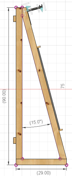
I will support it on the wall with two ledger boards that are attached to the studs, and will level it with some 2x or plywood feet (not shown).

On the bottom stringer board, I will drill out 1 inch holes for dowel rods that can slide forward and back to support the sheet material that is being cut, and on the top of the 4x8 have holes for dogs or clamps.
The top beam will be super strut that can be adjusted to the proper chain angle.
Comments, suggestions always welcome.
Thank you
2 Likes
That would make an attractive frame. Your thought makes me think that if you had a pre-built truss, you could chop it at the ridge (or whatever distance from the eaves is appropriate) and have two frame members.
Were you thinking of using the connector plates for trusses?
https://static1.squarespace.com/static/53442b51e4b072e71999c8c5/t/539650bde4b020ae6472cf40/1402360011174/trussinspec2
1 Like
Thanks @jwolter, interesting idea and if the frame does not work out I can take them out side and build a shed. -)
The truss plates are cheap enough, but to connect the frame pieces together I just used a pocket hole jig and 2-1/2 inch screws to toe-nail them together.
To secure the frame to the wall, I am thinking of using hurricane clips or some type of steel rafter tie

1 Like
I love this!
Thanks, @WoodCutter4, I actually using 1-5/16" Oak closet rod, left over from a remodeling project last year.
Where exactly did you shim the left support? I am trying to understand how that improved your accuracy. Also how did you determine that you needed to do that to improve accuracy? Thanks.
When re-measuring vertical motor offset I noticed, it was a tad lower on the left when comparing to center and right top beam supports. Instead of using multiple washers I just cut off a piece of 2" x 1/8" aluminum bar stock I had laying around and drilled a center hole for the bolt and wedged it between the beam and the support bracket.

2 Likes
I spent a lot of time hanging out and looking at different designs when I was planning and building my frame. So I promised myself I would post pics of mine when I was finished. I finished more than a year ago, but have since rebuilt my sled twice and only just got my machine calibrated again. Mine is probably sloppy and bulky and overkill, but hopefully something here can help someone who is looking to build.


1 Like