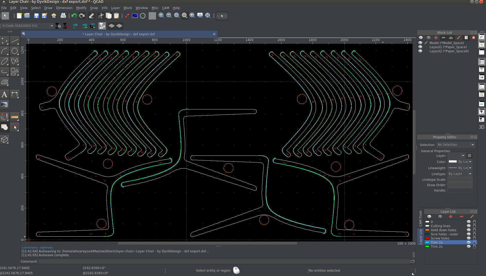
I’ll post a screenshot shortly. The only thing I can think of what those trimline could be for is for a rounding bit or so. They are not on all parts. The one layer called ‘cutlines’ and the layer ‘screwholes’ should do the trick, is my guess. The layer ‘holddown’ holes is not needed.
1 Like
The cutting bit diameter is specified in the fifth photo (screenshot) as 3.18mm, which is most likely the metric representation of 1/8". The MDF is 18mm thick, and the extra cuts are made at 6mm and 12mm to get the effect you see in picture three.
2 Likes
I expect the drill holes are 1/8" too, since it makes a lot of sense to reduce the number of bit changes. Plus the BBQ sticks they are using as dowels are probably around 3mm diameter.
You know, the designer has a comment system. You could just ask.
1 Like
I really think those lines are for the stepped edge effect as shown in the third picture.
3 Likes

Naturally. 
1 Like
YES. I only deleted the ‘holding down holes’ layer and stored as R12 dxf and then DXF2GCODE would load it.
Ony problem is that Qcad turned the 6.3MB file into a 58.8MB file, so you need to go and take a coffee until it is loaded.

So I take it I should stop trying to do this by hand in Inkscape and you folks will share a cut-able file? 
![]()
Have you tried Kiri Moto?

@dlarue I have not, but I will now.
@dlarue I assume it is possible to open a DXF in Kiri:Moto? Just looking at it now and it only seems to want to accept STL or GCODE
@ame You’re seeing this better than I am.
Couple of questions
- Which one of the trim cuts is 6 and which is 12?
- Are these bit changes or depth changes?
shoot and sorry @Chad_Marshall, I have used Kiri:Moto on STL files and just have confused Lightburn with Kiri:Moto for what files can be sliced. I too could not find it to import DXF files.
I was hoping Lightburn could be the magic tool but my little R2D2 on acrylic DXF exported to SVG by Lightburn didn’t look like R2D2 when I tried opening in Inkscape. YMMV
But Inkscape opens the R2D2 on Acrylic DXF file very well… I’m running the newest 1.1 dev branch though.
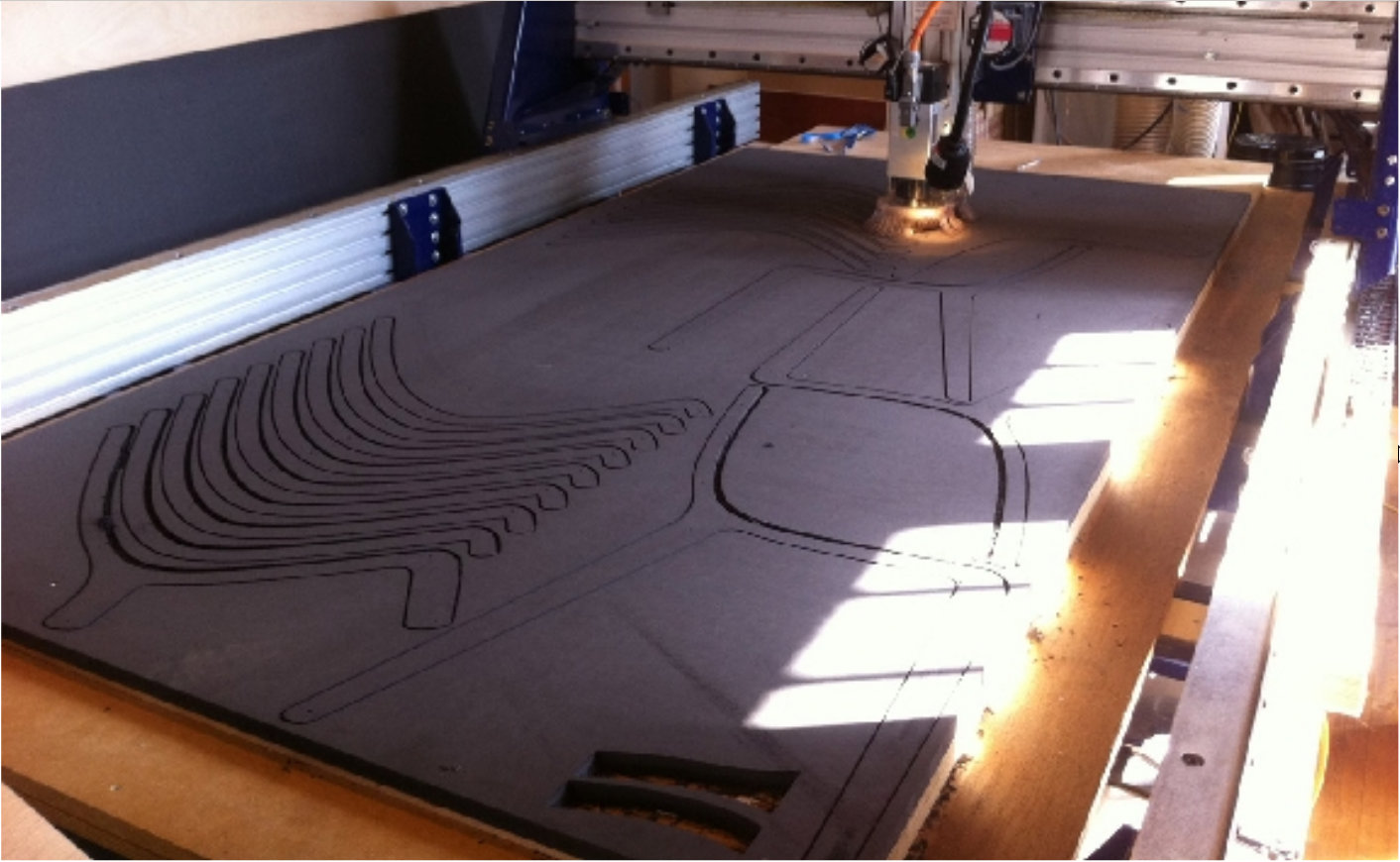
In picture three you can see that the pieces are all stacked up to make the chair, but they are angled/offset, so the extra ‘stairstep’ cuts make the edge ‘flatter’, otherwise it would be a very coarse ‘sawtooth’.
Not sure if the photo will embed properly, but this is picture 3:
![]()
The material is 18mm MDF, and the bit does not change (it’s 1/8"), so looking at the picture I am guessing that the top ‘stairstep’ is 6mm depth, and the middle step is 12mm. Obviously the full cut is 18mm, but probably you’ll have to do that in several passes anyway. In fact, with the rule of thumb that you should cut to a depth of half of the bit diameter, this is going to take a while. You might get away with a 6mm cut in one pass, then the top ‘stairstep’ is one pass, the middle one is two passes, and the full cut is three passes.
As to which trim cut is which, well it looks like picture three is taken from the top down, so you could find the outermost piece in the CAD drawing and look at the layers. The complete outline will be the full cut (18mm), and probably there are two lines that overlap the outline for the back and the seat, but not the legs. The innermost line would be cut to 6mm depth, then the other one will be 12mm.
The thing is, this is a complex job, and you need to understand precisely every single step from the idea, to the CAD, to the machine, to the final product. It is not enough to guess*, or just skip over things.
* I can guess because it’s not my project.
2 Likes
I too both looked at the original design and noticed the multiple steps in each cut segment. These steps allow the segments to be offset from each other and still provide a somewhat smooth interface to the body(human). Otherwise there would be larger corners sticking out as the author intended for there to be a curved effect.
Given that, I loaded the dxf into freeCAD and it didn’t look good. Took forever to load in bCNC and it too didn’t look like I could see many of the lines. But importing into Inkscape I could see all the lines and as mentioned, the offset cuts were there as separate splines and probably require a different diameter bit to get the effect. A different way to do it than a single bit and letting the cnc machine make multiple passes to get the effect.
Have you looked at what it takes in Inkscape to generate gcode? That’s how I would approach this. Figure out how to define different toolpaths and then start updating the design colors or layers so that Inkscape can generate the tool paths for the different parts of the design. It sure looks like all the parts of the design were imported.
Tell me more about R2D2 on Acrylic DXF please ![]() . Sounds cool. Pictures?
. Sounds cool. Pictures?
I don’t recall where I got it from but it was in my LaserStuff directory and it looks to be setup for an edge light type of thing.

1 Like
My apologies to the OP for going off-topic and BIG thank you @dlarue. Getting great result with acrylic and my desktop cnc recently. Will try to get more advanced in ‘bumbpmap’ creation and attempt a bit of depth. Should not be a problem with Gimp. Looking on
for a while, just did not have a file that would get me started. Have it now. Thanks!
Kind regards, Gero
In picture 6 you can see that the cuts for the end pieces (the chair legs) and the next inboard piece (looks like it has stubby legs) have much more material removed on the seat back and seat edges. This shows that the cutter has cut the outer profile and the two inner cuts (6mm and 12mm). Same tool (1/8"), different depths. I don’t really see what’s so hard to figure out.