TLDR: It’s a lot stiffer than than the current Maslow, at a trade-off some extra weight (~2kg, but we’ll see if that can be optimised), and reduced Z travel (I still get ~25mm of bit depth which is more than I need). Plus component cost + printing time of course.
I’ve been working on this for a couple of months and sitting on it for about a month because i’ve not been able to test it yet (because of a bereavement), but i’m just going to put it out there and hopefully i’ll get time to test it soon. I’ll have to post all the details in little chunks when I get 30 mins here and there (same reason), so bear with me. I should be able to do a build thread at some point with photos I took from the final build.
The problem I was trying to solve was that I was getting noticeable flex when doing X axis aligned cuts with a 1/4 bit (which is what I want to use to avoid bit deflection). As there was only Z height support on 2 of the 4 columns, I could flex it x-axis aligned. That is actually what triggered the Maslow 4x4 over-arching project i’ll discuss in another thread, but that quickly side-tracked into doing this conversion kit stepping stone.
Also it has a handle now, which is nice:

I’m working on a few designs, so to keep track of versions etc, i’ve stuck it in a fork on github:
(You can just download a zip of all the files).
It’s STLs because I started throwing things together in TinkerCad and at some point if it works well i’ll recreate it properly in a proper CAD package.
The README also has a component list that i’ll stick at the bottom of this thread.
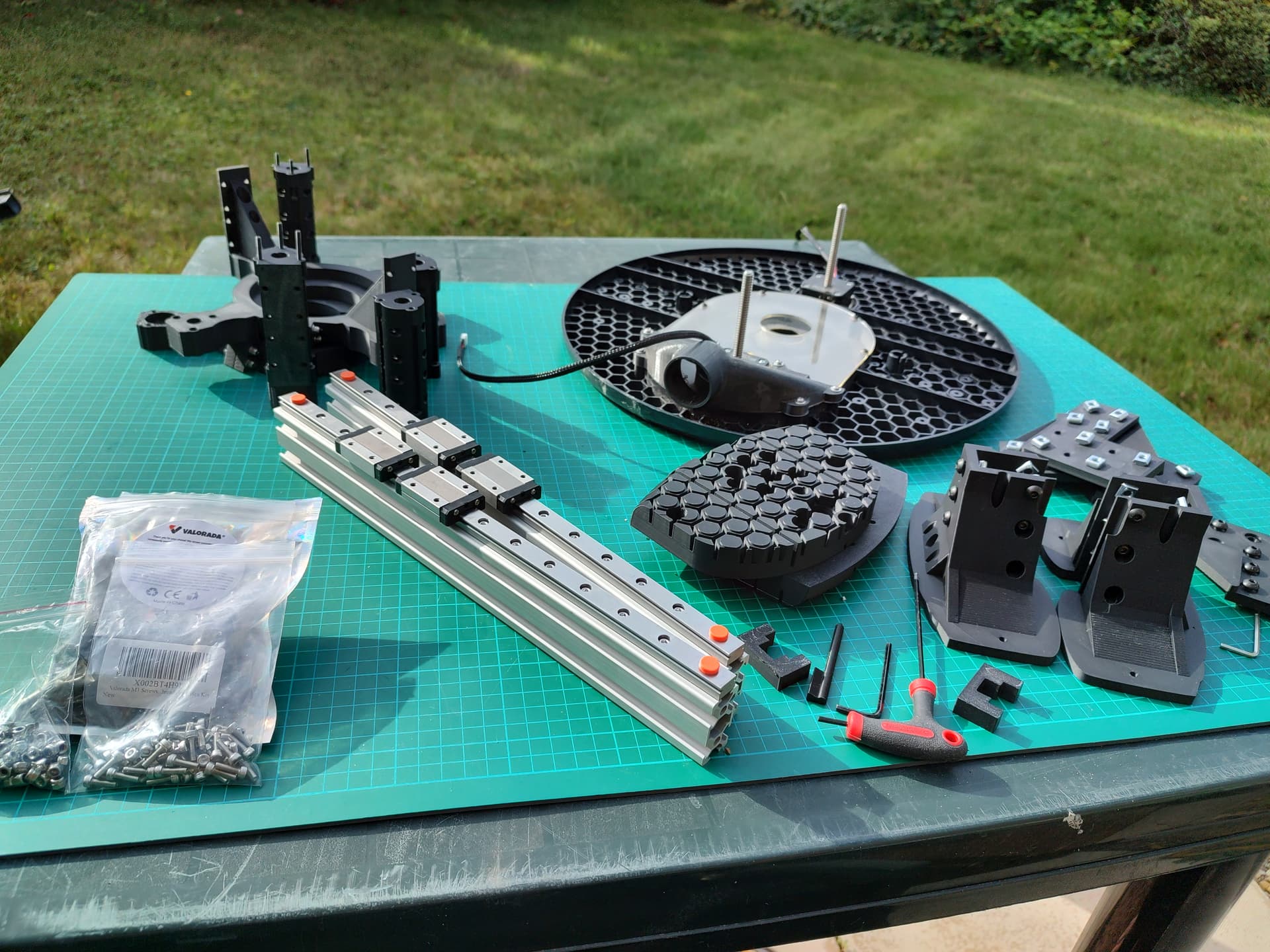
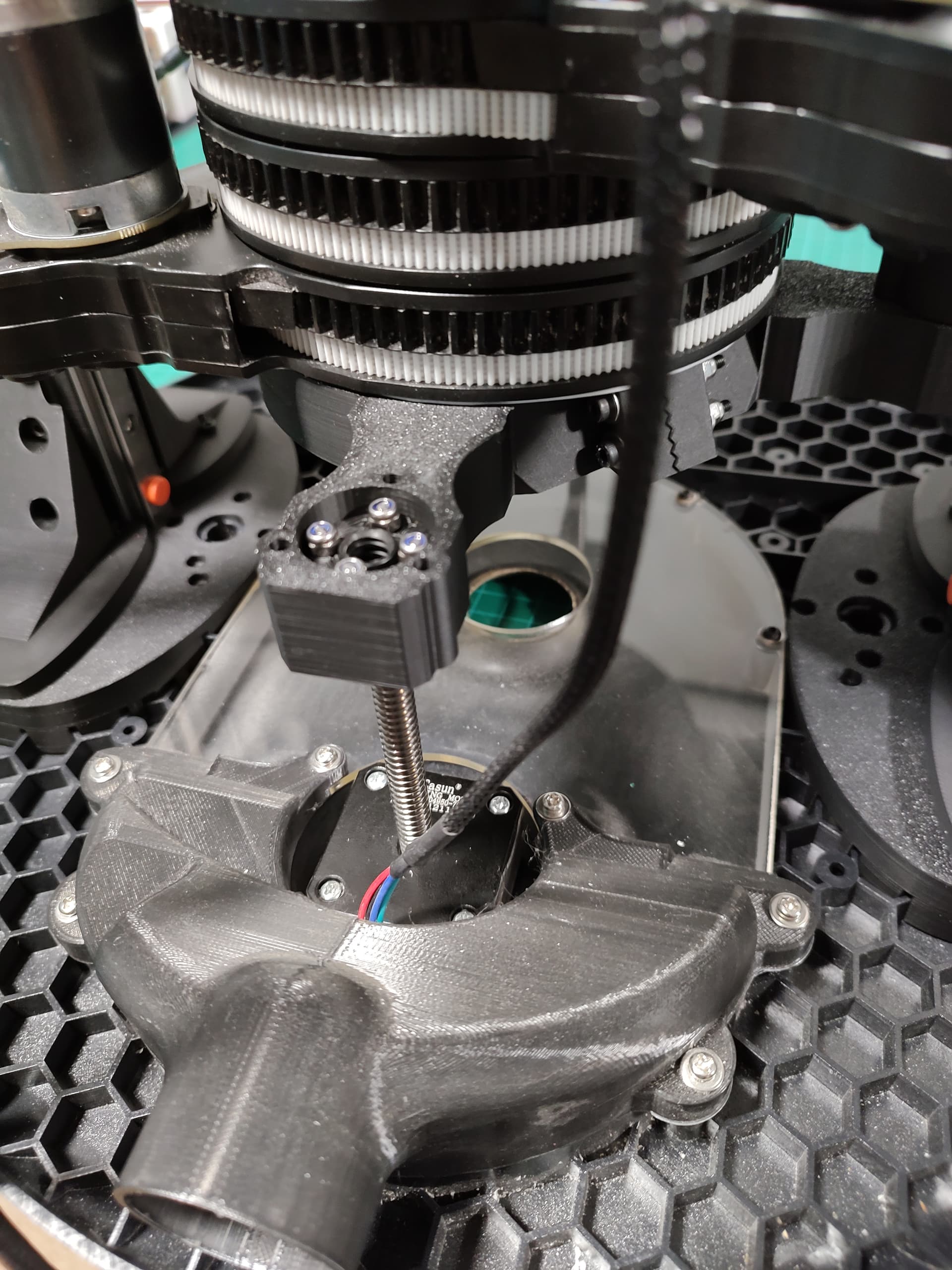
Here’s some random photos from when I built the latest version (1.0):


There’s a bunch of design decisions i’ll go into more depth at some point, but off the top of my head:
- The top and bottom clamps / plates are 20mm rather than 11mm because it adds a huge amount of stiffness.
- The extra 9mm goes up and down from the area that clamps onto the router - that bit is still 11mm
- The clamp is zigzag and 2 bolts to make it stiffer, it’s also sized quite carefully, to the point it should be tight when done up, but tape to pad might be needed depending on printer tolerance.
- The top and bottom can also be different because you’re printing them.
- Using 350mm 2040 for the uprights as well as the cross piece is deliberate - although it looks tall, the room lets you remove the router vertically to remove the arms without disassembling the sides, which are the bits that you need to fettle into place the most.
Non-printed components:
-
3 x 350mm 2040 aluminium profile.
-
2 x 350mm MGN12 rails (300mm also works but limits maintenance Z travel).
-
4 x MGN12H Carriage (2 per rail).
-
50 x M3 30mm socket head cap screws (includes spares).
-
20 x M3 10mm socket head cap screws (includes spares).
-
100 x M3 Locknut (includes spares).
-
10-30 x M3 washers (10 needed for router clamps, other per user preference).
-
M3 balljoint allen key (at least 100mm, the longer the better).
-
60 x M5 12mm button head cap screws (includes spares).
-
60 x M5 T Nuts (includes spares).
More when I get a bit more free time, but feel free to ask questions and I should be able to reply…