- Open Inkscape.
- Open svg file or new file
- Click Extensions on the menu and see if the gcodetools menu item is included. I read that it was included in inkscape as of version 0.90 or 0.91. I’m using 0.92.4.

If gcodetools is not included in your inkscape installation, you will need to install it (click arrow at left to see instructions
-option A. download gcodetools extension from github here or the direct link for the windows zip file here.
Windows
Unpack and copy all the files to the following directory Program Files\Inkscape\share\extensions\ and restart inkscape.
Execute python create_inx.py to create all inx-files. (The instructions I had did not include this, but I got it from the original author’s cnc-club.ru site not github. I included the github link to help. I’ve put a copy of the version I’m using on my github site here)
Linux
Unpack and copy all the files to the following directory /usr/share/inkscape/extensions/ and restart inkscape.
Execute python create_inx.py to create all inx-files.
- Set document to mm and size of cutout in mm (12’ =~ 300 mm)
File->document properties

- Create your cutout shape
after some editing, I have my shape as an outline only with the thickness of the line the same size as my cutting bit so I can see what it will look like.
if text, change fill to none, set stroke paint to black and stroke style to 3 mm or 4 mm (3.175 mm if you want to be precise) for 1/8" bit or 6 mm or 7 mm (6.35 mm) for 1/4" bit. This only matters because it helps you see the cuts that will overlap and where to put in tabs later.
Move the letters together so they overlap, convert object to path, cut path, then ungroup and then union it so it removes the extra lines. - Create a second layer, rename it “tabs.” Move it below the first layer as a matter of convention. I’m not sure if it matters what order it is in, but it works this way. In the layer viewer on the right, you can select which layer is visible by clicking on the eye. If the eye is black this is viewable, if greyed, then it is hidden. Don’t mess with the lock or you won’t be able to edit or select anything in that layer.
- Create a copy of your drawing and select the other layer and paste it. With both layers visible, you should not be able to tell them apart, but you can toggle which one you see hiding or viewing it in the layer viewer. If you paste it in and it isn’t lined up, you can move it and it will snap to the other layer.
after pasting, they may not line up, so move it if you need to.

- GCODE setup:
A. Create a tool for each layer: select each layer and do this step for each layer. I find it easiest to hide all layers, select the layer I want to set up, unhide it and then proceed. When finished, hide it, unhide the other and do it again.
Extensions->gcodetools->Tools library
select your cutting bit (cylinder or cone both work depending on the bit you are using) click apply. You will see a dialog box pop up while it works and then you can close the box. A new green box will be visible and associated with the layer you have selected. The second layer you do will have a blue box.
-Within that green box change the settings for your cut:
-You need to edit the numbers. Do this by double clicking on them and then when you get the text curson you can edit them. If your attempts to edit add numbers over the top, then undo and retry. or just click on the text and then click on the text tool bar on the left or the right side of the page.
-change diameter to 6.35 if you are using a 1/4" bit or 3.175 if you are using a 1/8th inch bit.
-Set your feed rate based on your material in mm/min (between 300 and 800). You can cut at 750, but it may not be good quality and your tool will dull faster if it gets hot.
-Penetration angle is always 90 for maslow because the router on the sled is flat on the work surface.
-Penetration feed is 800.
-Depth step is the depth your tool will cut in 1 pass in mm. You can do 3 mm step pretty easily. I’ve had success with 4 mm. I’ve done as much as 5 mm, but there is a proportional speed drop that must accompany it to keep the bit cool so you don’t overheat (Based on what I’ve read and the quality of cuts that resulted when I tried - your mileage may vary - I’d love to have more info on what settings to use to be efficient and high quality).
-Leave tool change as none.
B. Set up origin points with the same layer selected
Extensions->gcodetools->orientation points
orientation points tell your maslow where to cut with respect to home. Wherever you place the first orientation point on the left, that will be home. The second set of numbers represents your workpiece total cut depth that maslow will cut to in x passes of step depth defined in the colored box previously made. I’m doing 3/4" ply, so the total depth will be 19.1 mm. I prefer a -4 mm cut depth, so -4, -8, -12, -16 will be the cuts made on the “cut” layer. and the last layer will be the tabs. I want to cut to the left of the center home, so I moved my orientation points to the right. Always move the two points as a pair and do not change them with respect to each other. You can edit the right number if your material thickness changes.


- Edit the tabs.
-You need to first Hide the cut layer, make the tabs layer visible. Your green box and orientation points should disappear when you hide the cut layer.
- select your cutout, then choose the node tool (second one down below the select arrow.

-NOTE ON TABS: you will want to put a tab in on any completely cut out part. such as the center of the O, the piece between the M and E, and the little pieces between the O-H and O-M and of course the larger cutout and the sheet you are cutting from. I don’t have a good feel yet for how large the tabs should be. These ones will be 3 mm thick because the last cut will be from 16-19 mm and we are simply going to cut part of the design so it doesn’t get cut. We will start with the little one between H and O and I’m going to try to make it about 5 mm.

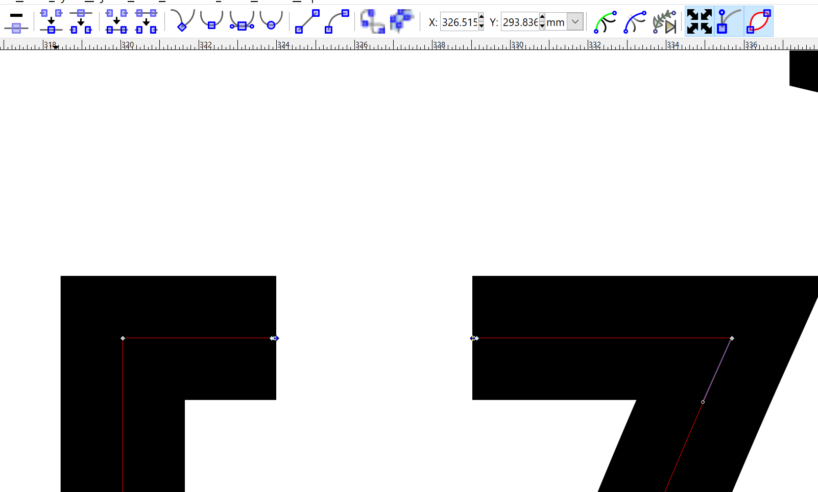
to cut the tabs, zoom in and select the cutout where you want to insert, select the two nodes where you want to remove the segment, and click the break node button above on the toolbar. If the nodes are spaced too far apart, double click to add a new node where you want to make your tab. If you are on a curve you might need to break the path first and then delete the segment.
Do this at all places you want to create tabs. I’m interested in learning the rules of thumb for tab placement. This could likely be automated with a script in inkscape if desired, but I’m not the one to do it. This is what I came up with:


- keeping the tab layer visible, add a tool and orientation points as in step 6
Should look like this.
the Orientation point start depth will be -16 because that is where the last layer cut stopped and where this will begin, so the tabs will be 4 mm thick and 5 mm wide.
with both layers visible, it will look like this with the orientation points on top of each other
- Make a header file in folder where you will save the gcode (only need to do this once)
text file name is “header”
I have these lines in my file:


G90 (absolute)
M3
G90 (absolute positioning)
G21 (All units in mm)
- Generate Gcode:
-First make both layers visible and select everything.
Extensions → gcodetools ->path to gcode
-click on preferences:
Enter the file name
enter the file path (only need to do this the first time as all these values are persistent)
Enter the height your Z axis is safe to move over a blank (I use 5 mm)
units are in mm.

-click on path to gcode tab

depth function is d, cutting order is path by path (cuts entire job at each depth), if you do path by path, it cuts each path segment layer by layer, so it will cut part of the H 4 times and then move to the next piece completing all of the cut layer then go back and do the tab layer.
-If the preferences tab is selected, it will not generate gcode, so make sure the path to gcode tab is selected then click “apply”
an error will pop up, always does.

click ok then you will see this if it is working:

It will take a while depending on how complicated the cut is and how many segments there are.
when the working dialog closes, it is finished and you can close the path to gcode window and go upload the gcode file.
That’s it. If no gcode is generated, then there is a problem. Double check your numbers and try again.
Good luck!
EDIT: One last point of frustration. between each segment, the generated gcode raises and lowers the z axis. I started taking those out and it really speeds things up because the stock z axis is super slow, but only take them out if the location before and after the segment change is the same.


