I think github ‘really wants’ to use links to images stored elsewhere for pictures in a wiki.
I think that to store them within the wiki structure will require going through the Pull Request procedure. Have you cloned the wiki (“https://github.com/MaslowCNC/Mechanics.wiki.git”)? Once cloned, add a directory ‘Images’ - if it doesn’t already exist, and put your files in there. Create a PR to merge back to the master, and once it is merged you can use . Hence Motor-Encoder-Gearbox-Chain
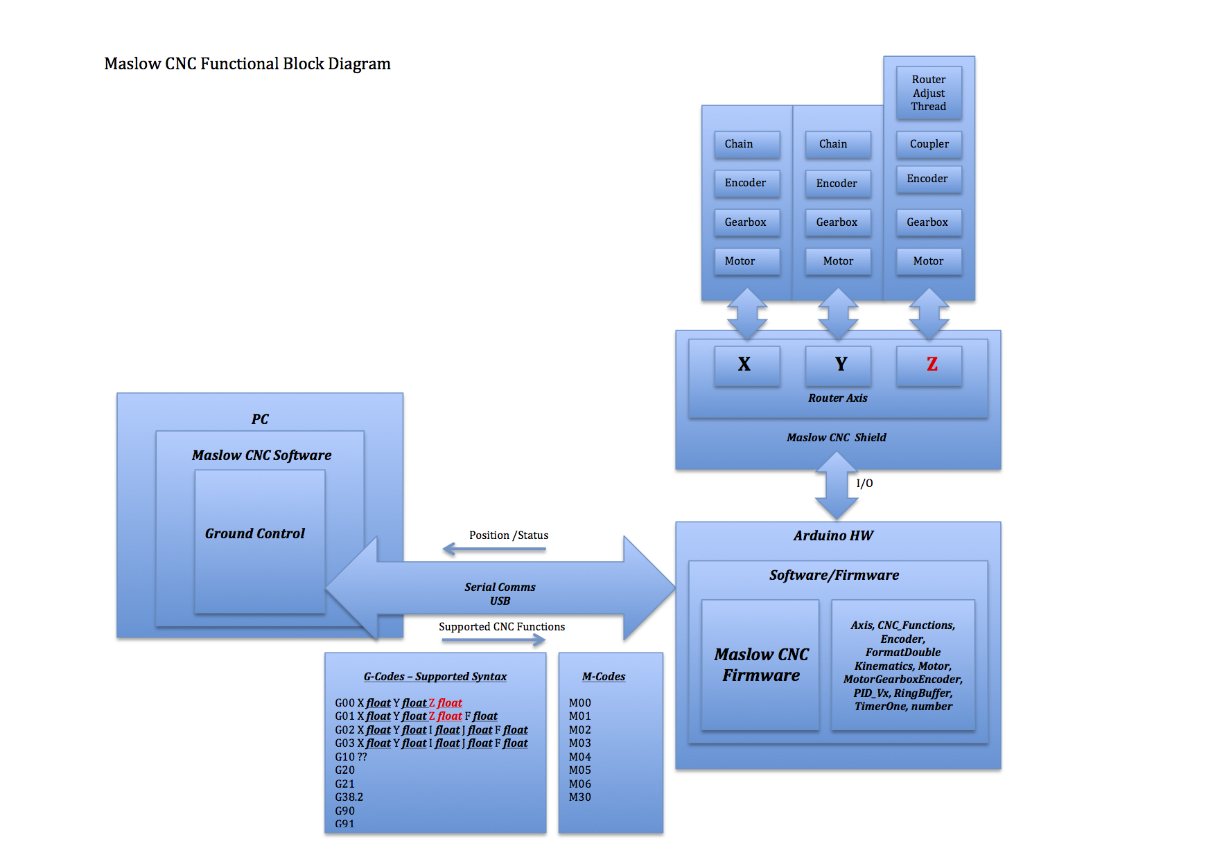
Perfect thanks Blurfl. The image has been updated on the Function Block Diagram wiki area.
I am thinking of putting in a layer for the sled for completeness.
What I am thinking here is
The Chains connect to the Sled via a mechanical mount. This will be left generic as currently there seems to be a couple of variants that impact quadrilateral or triangular kinematics (basic mount, Linkage kit, )
Chain / Mechanical Mount / Sled
The router connects to the sled via mechanical mounts as does the Z Axis
This should leave us with a complete view of the system as is.
There are some system variables related to the sled, so it makes sense to capture all that in a sled block. What information will the router block capture?
and the system variables are vastly different for the two kinematics models,
they will need two different diagrams.
I would suggest using the simulator to show the types of errors that happen with
each variable being wrong (possibly one picture if the value is too large, and
another if it’s too small)
Dlang,
I see these as specific links on the Diagram noting that the kinematics are actually different.
Please see the updated version of the Functional Block Diagram to indicate what I was thinking. I will indicate that the X & Y Axis motor assemblies are actually mounted to the frame but think this is an improvement and closer to the final diagram.
Blurfl,
I have added your suggested changes and am slowly progressing the Function Block Wiki. I have added in sections on the H-Bridge functionality concentrating on the Motor Shield at present.
Which ones were you referring to. I had to show the inverted state on the and gates, the ones with the circles even though the input is reverse. The output of the and gates should be correct.
Blurfl
I finally clicked on the link so can now see what you are referring to. My logic is correct but I do like the colour coding. When I get the chance I will revisit. Great link.
Doing the PWM and quadrature encoding sections tomorrow.
Thanks Blurfl, That was because of the inverted input but what I can do it put that logic in and for those confused by the inverted input signal an show the and logic.
I will also indicate that the 1 represents the logical high (ON) and Zero as a logic low (off).


