Please note that the 40mm version in the STEP files above has the wrong spacing for the two holes at the front (nearest the router). I haven’t checked the rest.
@bar Is there any chance of getting the STEP files for the current design in the Not Shop? Bonus points for the original design files
I’ve a version designed with the locking mechanism for the Festool D27 style connector but it was based on the old STEP files so doesn’t fit. I’d be happy to share once I have the correct design.
Folks, this is my spin on the PCB mount for the DeWalt 26200 which has a slightly different mounting pattern for us East-Pondians.
This is based on the footprint created by @geertdoornboshere but I wanted to rotate it slightly to avoid the clash with the power cable on the router. I was too lazy to do the neat fitted version which may result in a debris trap but time will tell.
One thing to note, the mounting post circled in the image below is behind the power cable on the router and this makes it a bit awkward to access. If I could be bothered to print it again I’d probably rotate it (the angle is a parametric value in the Fusion 360 file) so the PCB power connector is on the other side of the router power cable Ignore this, I just realised the router power cable would then block the stepper motor connectors.
Thanks @bar for uploading the new dust shoe STEP files to the GitHub repo.
This is my remix of the 40mm connector version. It’s just a slightly extended nozzle and locking pins / slots / thingamajigs for the FesTool D27 type hose connector.
A version of the 40mm dust shroud without the two holes at the front that clash with the acrylic plate (left on the picture VS theNotShop version on the right). As I modified the stl file directly, I have no step version to provide. Thanks for the original design, and feel free to share it in the notShop!
I’m wondering if files for all the plastic parts for Maslow4 are posted somewhere (print replacements, modify for improvements, or for reference in modeling accessories). I’ve looked around a fair bit, but without success. I very much appreciate the help, I know it takes someone else’s time to reply so I try to put in good effort before I reach out. Hopefully I haven’t missed something painfully obvious.
Pen holder for plotting/testing patterns. Using a Pilot G2 pen, cut down to 2.4" Overall Length. Simply screw into dewalt 611 where the collet nut normally goes. Use spring from pen to help keep it down on uneven surfaces
Yes it did work well! I set to run Z-.05in to keep the spring under pressure. The only issue was the sled was gripping the paper in my horizontal setup here. Skipped along a bit and not all patterns’ start and end point match up.
Need to do something to lessen the friction with this brown packing paper… Has anyone done any kind of ball bearing roller setup for the bottom of the sled? Or wax paper layer, etc.
Need to do something to lessen the friction with this brown packing paper…
Has anyone done any kind of ball bearing roller setup for the bottom of the
sled? Or wax paper layer, etc.
people have waxed the bottom of the sled or put slippery tape on the bottom of
the sled.
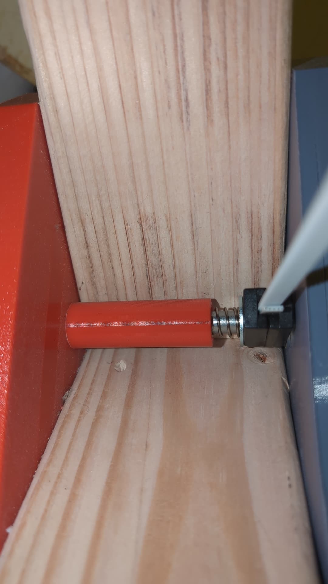
Spacer to keep the belt ends stable on the same Z plane. Helps with accuracy and calibration.
Create a STL with OpenSCAD, modify as needed. I have the smooth side of washers facing the faces of the belt ends. The spring is very lightly compressed.
Forgive my newbie question here… So, if I’m getting this straight, the belts come off the M4 at four different heights because of how the M4 is built. Does that mean that on a completely flat frame, these four attachments at each corner, where the four anchors connect, make sure each belt stays perfectly horizontal, which then significantly boosts the fitness results? Am I on the right track?