Brilliant!
Can I share this in next week’s weekly update (giving you credit of course)? I bet there are folks out there who will benefit who might not find it here on their own
Brilliant!
Can I share this in next week’s weekly update (giving you credit of course)? I bet there are folks out there who will benefit who might not find it here on their own
Sure!
Maybe add to the Not Shop too?
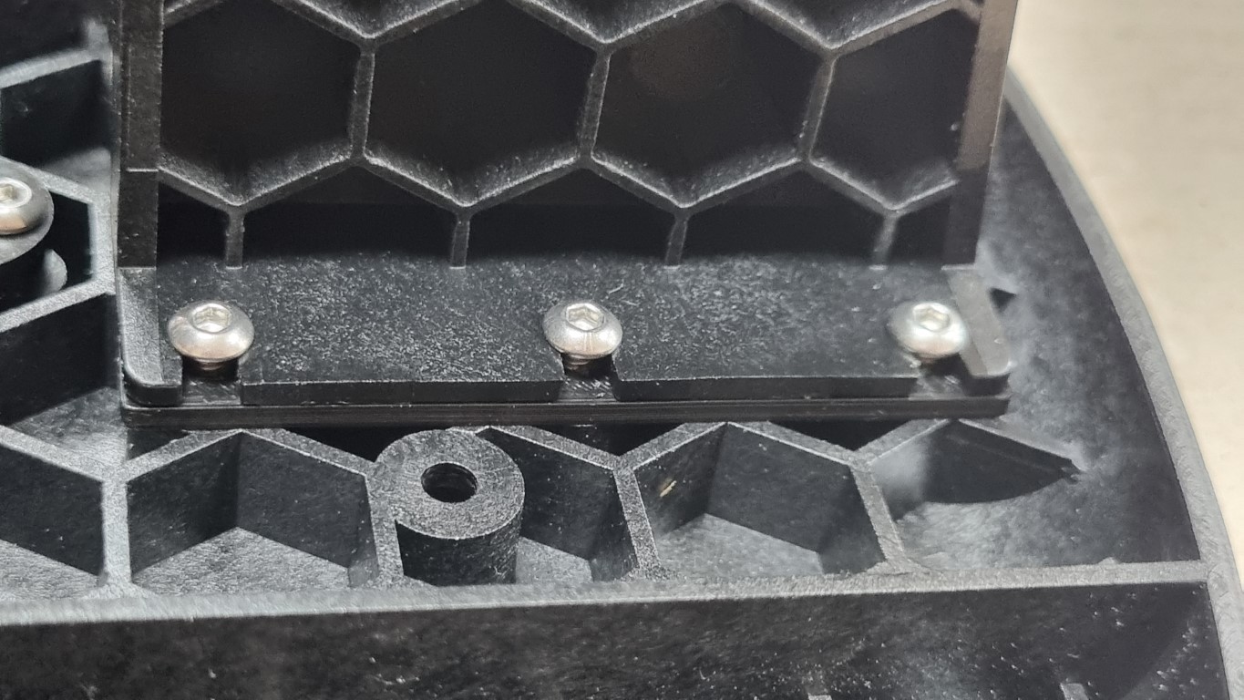
The rods are a good fit on the sled. Looking from the bottom side, there is no spacing visible. I could have shortened the rods, but that’s pretty definitive. With some washer of different thickness, I tried to determine the extra distance and ‘measured’ 2 mm.
I 3D-printed a filling layer, mounted it. A good fit with no material stress and parallel rods.
Linear Rod Support Fill v1.f3d (50.1 KB)
Linear Rod Support Fill v1.step (23.9 KB)
Linear Rod Support Fill v1.stl (37.0 KB)
Interesting. I definitely spent 20 minutes going around and around very gradually tightening those with an Allen key instead.
Of course on the other side I found my 2mm screwdriver and it took 2 minutes ![]() .
.
But this discussion is interesting.
In the “Assembling the arms” section, the portion regarding gluing the magnets into the rollers ends with the admonition;
Now set those aside to dry. Be careful not to put them too close together while drying because the magnets will attract and stick together. You have to place them further apart than you might expect.
What it doesn’t tell you is a handy means of maintaining the spacing is provided!
(Just be careful not to glue them to the sled…)
Me too. I just tightened them like lug nuts in an every other screw, then skip 2 pattern and got mine all the way down with little effort. And at a certain point they seated a bit deeper in the tops of the towers.
I measured my two rods and one was 0.625" longer. I just shortened the long one.
5/8" ?
I noticed that some of the belt ends aren’t cut squarely in a gullet- they look like this
whereas I think they should look like this
If the ‘ragged’ end is too long and is inserted into the spool, you might only be able to engage three of the teeth in the slot
instead of all four
I trimmed the affected ends with a pair of tin snips to square them up. If you do this, remember that the belts have steel reinforcement- don’t use cutter intended for soft wire (like the flush cutters pictured below) to cut the belt, you’ll permanently damage the cutting edge.
Missed a zero there, the correct number is: 0.0625"
Thanks for sharing that pointer!
With all the comments regarding high current requirements to retract belts and hopes that break-in would alleviate it, I felt that some lubrication might be needed. I didn’t want to use anything that would collect debris- so no oil or grease- nothing conducive in case it found its way into the router or electronics- so no graphite- and it had to be inert due to the variety of materials present. I ended up using powdered PTFE. I applied it to the contact surfaces of the arms and spool during assembly. I don’t know if it made any difference, but I can extend and retract each spool with a setting of 1200.
I did also note that the interference fit between the drive and idler gears was notably tighter on two of the arm assemblies than on the others. I don’t know if this could be another factor and it was not clear where the source of the variation lies. In hindsight, I should have swapped around parts to try to find any pattern- maybe on the next teardown.
I built my first Maslow 4 this weekend, and I noticed many of the same issues as everyone else.
As @CPL reported above, I also noticed that it was a tight fit between the drive gear and idler gear. I also had one or two belts that didn’t fully retract when I did the Retract All. I did run the Extend All and pull a few feet out on each belt, then another Retract All was successful.
As others reported, my linear rods didn’t seem to be cut perfectly square, and were not the same length, one was ~211mm, the other was ~212mm. I made shims from old credit cards to put under the support risers to adjust for the lengths. Also, when I went to put the first support riser on, it seemed to me like the linear rod wasn’t perpendicular to the sled. I should have grabbed a square to check, but instead I just loosened the linear rod clamps so the rods would move, then installed the support risers, then tightened the linear rod clamps back.
To me, the most difficult and frustrating part of the whole process was trying to get the belt ends on the belt. Once I finally got the belt in one half, getting the other half lined up and getting the belt in was still difficult. What helped me was putting the two halves of the belt end on one of the linear shafts to keep everything lined up. Once I got the belt started, I used a clamp to push the two halves together before putting the bolt in.
When it came to pressing the two halves of the arm together, I actually found it easier to put the rollers in the arm half that the motor is attached to. Then I worked with the motor down, which made it easier to see that the rollers and drive gear were lined up with the bearings. Once I felt everything was lined up, I used the handle of a screwdriver to tap on the non-motor half where the recess for the idler shaft is to get the idler shaft seated, and they generally went together easily.
I think I made a mistake in my assembly…
I just bought a vacuum adapter from the etsy shop listed in your last update. When I tried to fit it to my maslow, I noticed that the left side is built with some relief for the belt arm. On my maslow, its the arm to the RIGHT of the power cord that is lowest in the stack, and needs the relief in the vacuum adapter. I was confused by the directions in that part of the assembly guide, since I had the router inverted when I was stacking on the belt spool/arms, I apparently misunderstood the directions as to order of assembly and specific direction each one was to point…
I also believe that the vacuum adapter needs an update to the model… The two mounting tabs on the top/inside, that share a mounting screw with the clear shield, should be raised by the thickness of the clear shield, so that the adapter will sit flat and seal well along all of its edges. I realize that this will necessitate some support material below those tabs in order to be printable…
I had this same issue. the order of the arms is supposed to be (looking at the maslow while its on its sled, bottom to top…) lower left, upper right, lower right, upper left. Bar also has a video on the assembly page with the opposite order from top to bottom.
Now, I broke it. When I disassembled it this morning to rearrange the arms, I discovered that the clamping wedge on the lower router clamp has snapped in two pieces. Have you got a spare you can send me?
See attached pic.
Absolutely, shoot an email to Anna@maslowcnc.com and we’ll get you one in the mail ASAP
Here’s my resolution to the problem of the vacuum adapter mounting tabs. I cut them off, then rummaged around my ham shack, and found some ‘solder lugs’ from the old days of point to point wiring. I anchored them under the screw heads for the clear shield, and after mounting the vacuum adapter with the other four screws, I rotated them over the vacuum adapter and tightened those screws.
Secure with no leaks.
Here are a few notes from the first two live stream sessions which covered the assembly and firmware update.
Assembly Guide
Installing the gears in the arms: I found that not fully tightening the screws that attach the motor to the arm case allows things to shift a little when installing the idler gear.
I found that using one of the rollers to press the bearings into their places worked well, but by the time I had finished, I had chewed up the end of the roller a little. To get the chewed end into the bearing, I had to sand it down a little.
When installing the first clamp to the router, the instructions don’t say how far to push the clamp down. I ended up pushing it all the way until it bottomed out, and that was apparently the right answer, but it would be better to explicitly state this.
I have lots of issues with the instructions and video about adding the arms to the router.

User Guide
The instructions for uploading new firmware describe the process for installing the firmware before describing how and where to get the latest firmware. Since the user may need to switch from Internet wifi to maslow wifi between these two, getting the files should be described first. As others have mentioned, the instructions should state that the other files (index.html.gz and maslow.yaml) should be updated every time the firmware is uploaded.
(edit) I recommend a warning to inspect the belts to make sure they won’t catch on anything before the initial “retract all”. I discovered the hard way that there was a knot in one of my belts!