I can’t the way I built this model (and it’s a pain to do as you have to precisely position each hole, good for engineering drawings, massive overkill for woodworking)
it lists export options for sheets as
dxf
dwg
dwt
pdf
for dxf/dwg it gives the option to export as text or explode into polylines
and there is a ‘export all sheets’ or ‘only current sheet’, which apparently isn’t working correctly
but if it’s all individual lines, like the svf/pdf, that doesn’t help anyway
Maybe I can do all in inkscape. I can make the fasteners in visio, save as svg, and import into inkscape and just copy and paste. Since there are only a few orientations it might not be that difficult.
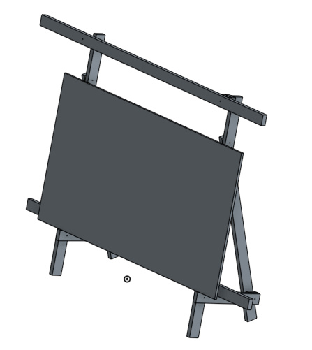
Here is the 2D Cad of my proposed design in scale. The top beam can be Unistrut or 2x4. As this is only 2 2x4 it’s rear depth is ~ 7 inches with 1 folding leg. The top beam will come forward the distance of a 2x4 plus the motors I would say ~ 5.5 inches. It’s rigidity comes from 4 tie points of the 3/4 plywood frame on the front, tide to the 2 parallel vertical 2x4’s, that are tied by a diagonal 2x4 beam.
thinking about the panel saw, it doesn’t need to have rollers, something that just hooks over the top beam would work. I’ll do up a CAD of it after I finish doing the assembly step diagrams
I’m planning to use ours as a 2-axis panel saw. Fix the horizontal travel and you cut from top to bottom. Fix the vertical and you cut from side to side.
I love the cutout layer in the carriage shaped like the saw baseplate so you always position it the same way. Once I get my Maslow up, I’m gonna cut one of those. Thanks for posting!
I’ve had an idea for a similar unistrut panel saw for some time. I was thinking of fabricating glides like these instead of using bearings. The unistrut for the vertical rails would be rotated 90 degrees so that the open part of the channels are facing each other.
I’m thinking 2.5" screws (3" screws would have a tendency to poke through if you
slightly overdrive them, and while they would be better if every one was driven
in at a slight angle to avoid this, people aren’t going to do this.
and in any case, the glue should be the main part of the strength, so 2-4 2.5"
screws per 3.5x3.5 overlap should be good.
Our Unistrut is set back behind the plane of the workpiece so that if/when
the sled overruns the end of the work area, hopefully the router bit won’t
try to take a bite out of the Unistrut.
Throwing in my modified frame design.
I extended the 2X4’s that hold the waste board, made some brackets out of flat bar that hold a 10’ section of 1" square tubing that I mounted the motors on. Seems to work pretty well, doesn’t change the original design much, and uses common materials.
Would it be safe to say that someone could take their stock final frame and achieve the same accuracy improvement that this frame is thought to provide by basically adding a new 2x4 to the side of each existing legs and building the top beam off that? I don’t think the back leg on the stock frame reaches as high as what is shown in the new design, but is that critical?
(This doesn’t address things like eliminating the bottom beam and the wings for the stretchy string and any other stiffeners… just talking about the top beam)
The big drawback I’m seeing now when I look at the cut list is that you end up with some extra length on two of the 2x4s. Overall it takes six 10’ 2x4s and removes an entire sheet of plywood from the BOM
What about not going with all 10’ lengths? Four 10s and two 8s?
I can get as short as 93" (stud length) at my local stores, and as long as 16’. There may be ways to pick and choose appropriate lengths that are not 10 footers.
Many places also sell partial sheets of plywood, but one could always use a full sheet for calibration and test piloting the machine