Maslow S: Wood arms glued and screwed into the leg with top beam resting on the arms attached via two simple L-brackets.
Maslow SL: All features of S-model with unistrut arms and top beam for adjustability
Maslow SLE: All features of SL-model with rear plywood storage
Maslow SLT: All features of SLE-model with cup holders
Maslow GT: All unistrut construction
4 Likes
![]() Now that’s the version I want! Never underestimate the value of being able to drink a beer while the Maslow is cutting!
Now that’s the version I want! Never underestimate the value of being able to drink a beer while the Maslow is cutting!
But what about a GLT version?
2 Likes
I know from experience that you are going to end up cutting up the frame
plywood, not just your wasteboard
Clamp, or temporarily screw or nail the joint together before drilling the hole (and after double checking with your speed square  ). Remove the afixing device(s) and install the bolt, or bolt first if you’d rather. Unless you’re way off it’ll stay in place
This is what the joint would look like as you are mounting the bracket to the leg (with the top beam moved back a lot so it’s balanced to not fall down.
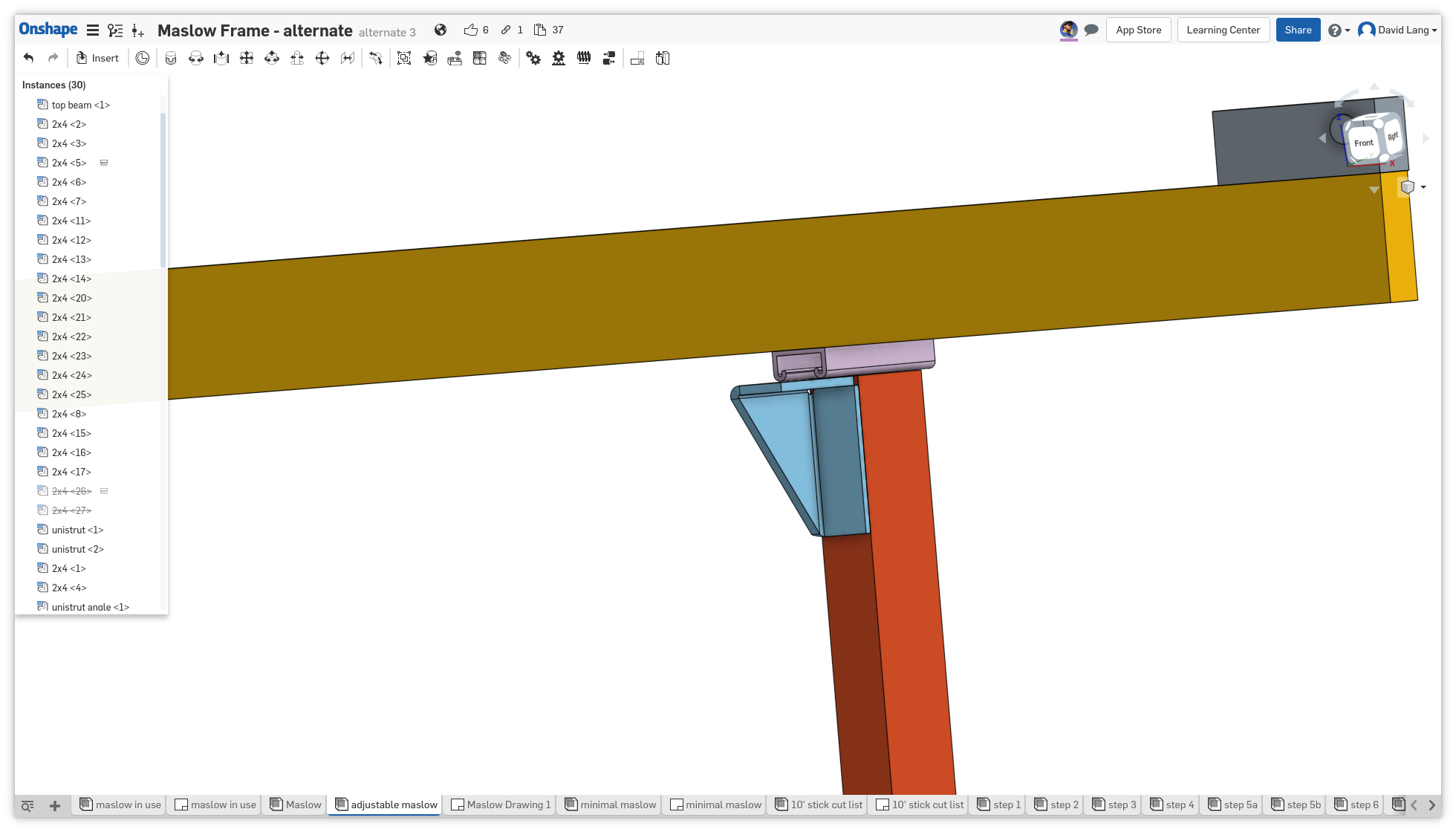
I haven’t modeled the bolt holes in the bracket
this will be very square, and the unistrut to top beam will be very square, and the result is adjustable and easily reaches the distances we need with a 6" unistrut, and can be extended out to arbitrary distances by people who need more.
I am in the process of finishing up my new frame and was wondering why not install a 2x on either side of the front leg and then sandwich a one more 2x between them for more support, like the following in red.
I wonder if there would not be too much chance of the strut being loose on the backside, I would think that you would have to notch the back as well as the front so that it could be tightned down @dlang 
ideally two bolts up a couple inches apart
with he gusseted brackets <$6 each, they really seem like the easiest, and most reliable way to make this joint.
two arms would be overkill, one is plenty strong
@Bar, have you looked at using your sled L-brackets instead of a stack of 2 x 4 pieces for mounting the top beam? I found that they worked pretty well.
1 Like
they don’t have enough of those l-brackets
how far out did you get the beam moved using them? you should have about 6" from the front of the leg to the front of the eam.

That’s odd, I measure in the neighborhood of 4" from the front of the beam to the face of the 2x4 upright. That places the chains parallel to the workarea surface on my rig, with a 3/4" workarea and a 5mm spoil board.
Is 6" based on assumptions about sled thickness and linkage standoff height? Those are quite variable. I chose my standoff height to match the height that balanced my quadrilateral sled, seemed a reasonable choice. The sled thickness is part of that height because that’s how I made the measurement, from the chain to the work surface. I’ve put quite a few miles on the rig with this geometry, the chains seem to run smoothly.
1 Like
back around post 151 we had this discussion:
Bar did some calcuations and came up with a smaller number (forgetting the wasteboard and the material being cut) and we eventually ended up with a target number of just over 6 1/4" from the front of the leg to the chain. I’ve been using 6" as a nice round number.
you are using a shorter spoilboard.
the weight of the bricks you use will affect what the proper balance point on your sled is.
This is why I am pushing the idea of the adjustability ![]()
I believe that the original motor mounts put the motors out approximatly 6 inches from the front of the 2x4 (they were 8", right?)
Well,I did quite a lot of cutting all ready and didn’t go through it yet.
The z axis is accurate enough.
seems like there is no reason you should go through it unless an accident happens. And even then, if you are monitoring, then you could stop it fairly quickly
3 Likes
when you have experimenters creating the g-code, it’s all to easy to make it go too deep, and while the maslow is slow, it’s not always obvious when you are too deep (and a lot of people are not going to be paying that much attention a long time into the cut). Getting a faster Z axis (which we should do), will just make it easier to have a problem.
We’ve had people have their router pop loose and the bungee cord drive it to full depth into the wood and frame. We have a very primitive g-code parser that ignores codes it doesn’t understand, so if you have the wrong g-code, it can end up flipping the Y and Z axis, and try to go down deep into the material (and with the router we have, it will cut down like that)
1 Like
But things like that don’t happen on a daily basis and you’ll need a lot of those mistakes before you have to replace the 4x8
2 Likes
That’s true, but we’re still designing the machine to support it. It’s not that much more in stick lumber
also, some people are interested in using foam as wasteboard, and you need more thickness to be stable, being able to eliminate that 3/4" helps make room for it
I think that is the main factor here. People are going to do different things depending on their use cases. No one design is going to fit all, and this thread is trying to define what is necessary and how to accomplish that necessity in the easiest way possible. Everyone has put forth great ideas, and it is really difficult to parse those great ideas out into the best yet simplest design while still creating something that isn’t unduly temporary (and in need of immediate replacement).
2 Likes
our goals
- no temporary frame (which means no CNC cut parts)
- very rigid relative positioning of the motors (top beam support)
- able to be built with minimal tools (currently aiming at)
- drill/driver with drill bits
- tape measure
- square of some sort (speed square is cheap and effective)
- saw (including a hand saw)
- wrenches/socket set (not a hard requirement yet, may be bits for the drill/driver)
- pen/pencil to mark cuts
- fit through a normal doorway (80" tall, 28" wide)
- only include parts that you can get at a local lumberyard (everything else must be included in the kit)
- work with the exiting motor mounts (since they have already been purchased)
we are trying to avoid critical angles or measurements, especially ones that must be marked and be the same in multiple places.
Where it’s important that two measurements should match, use a spacer to make sure the multiple instances are the same.
3 Likes
here is a copy of the page I have going on the wiki at https://github.com/MaslowCNC/Mechanics/wiki/Feb-2018-Frame, but with the basic images added (getting them on the wiki is non-trival, and we would like to have @madgrizzle color-code and label everything, as well as showing the connectors.
This is based of the onshape document at https://cad.onshape.com/documents/e635c24e358635f51da4b399/w/d1c80dfcda96cf52fab821ed/e/686708f4e7fa5bec934ada23 specifically the brand “alternate 3” and version “v13”
Assembly Instructions
Assembly instructions for the Maslow frame. This process deliberately avoids specifying measurements. Instead everything is positions by using other boards that have been cut as spacers. This produces more consistent results
The only measurement that’s needed is when you are squaring the frame, and that can be done with a piece of string (just use something that doesn’t stretch)
To keep everything square, you want to have a factory end on the 72" front legs, one of the 60" back legs, the 10" top beam supports, and two of the 24" pieces for the rear kickers (I’ll post a revised cut-list to show this grouping,probably graphically)
When fastening with glue and screws, the main purpose of the screws is to hold everything together while the glue dries, but they also provide a backup if the glue fails. “real woodworkers” can flatten/sand the surfaces and glue and clamp instead of screwing and end up with a good, strong joint. Normal people should leave screws in place 
This is ordered to keep things as small as possible as long as possible so that most of the work can be done on a bench/table
Options
There are a few common variations on this frame
- Folding Frame
Allow the rear legs to fold up to the front ones to allow the machine to be stored in less space - feet/casters
Clean up the legs where they hit the floor and attach feet or casters to level/move the machine - additional wasteboard support
Some people live in areas where the temperature/humidity can change rapidly, this can warp the plywood. Other people are experimenting with using sheets of foam for the wasteboard. By adding a couple extra boards to the Maslow, the main plywood board is not needed and the wasteboard can be mounted directly to the frame - Support for cutting extra thick/thin material
By default, the Maslow can cut material up to about 1" thick, this variation allows for more thickness - unistrut top beam
Unistrut is a metal beam commonly used to support pipes and conduit in industrial buildings. (in the US, Home Depot and Lowes carry it, but not always in stock). It is a 1 5/8 (41mm) channel that is designed to hang things from easily. It is available with holes already in it and will be a little stiffer than stick lumber and will not distort with humidity changes.
Assembly Instructions
-
attach lower blocks to front legs
- take a 60" rear leg and clamp it to the side of a front leg with factory ends together and flush.
- put a spacer block narrow side against the bottom of the 60" piece
- position the block to be attached against the ground and the spacer block end grain of the block should be against the ground
- Check that it is square and fasten it in place with glue and screws.

-
attach kickers to front legs
- use spacer blocks under the combined legs to lift them 1.5" off the ground
- move the rear leg and spacer block to the other side of the front leg in the same arrangement as step 1
- the spacer blocks attached in step 1 are on opposite sides of the front legs (the inside of each leg)
- position the kicker against the ground and the spacer block (on what will be the outside of the front leg, so one on the left and the other on the right).
- Check that it is square
- Fasten to front leg
Option if you are building a folding frame, drill through the kicker, leg, and block to fasten with a removable bolt. For now, tighten the bolt so the kicker cannot move.
otherwise, fasten it in place with glue and screws
IMPORTANT: This is one of two places in the build where the angles and distances are critical. Make sure that the kickers are as square to the front legs as you can make them. Use the same pieces of wood as spacers for attaching the kicker to each of the front legs.

-
attach the leg spacer to the front legs
- position the rear leg next to the front leg, with the bottoms of the legs even.
- place a block between the front and back legs at the top of the back leg
- glue and screw the block to the front leg.

-
attach the rear legs to the front legs
- drill through the back leg and use a lag bolt to attach it to the block installed in step 3 (or optionally drill through both legs and the block and use a through bolt)

- drill through the back leg and use a lag bolt to attach it to the block installed in step 3 (or optionally drill through both legs and the block and use a through bolt)
-
position the top cross-member block
- take the two 24" diagonals and set them against the lower block
- position another piece of lumber above the block, clamp in place (see diagram 5a)

- remove the two diagonals
- position a 2x4 spacer block on edge below this clamped piece
- position a block flat against the leg, with the grain forward (see diagram 5b)

- glue and screw the block to the front leg.
IMPORTANT: make sure the block does not slip and extend forward of the front leg, with the kicker sticking forward of the leg it will not sit flat on the ground
-
angle the rear legs
- pivot the rear legs so that the edge of the leg and the bottom corner of the rear kicker line up, the top edge of the kicker will extend slightly beyond the rear leg
- glue and screw in place)
-
Option if not building a folding frame remove the bolt joining the legs (step 4) to add glue and replace the bolt

-
connect the front legs with cross-members
- attach one 82" cross-member across the top of the each of the set of blocks attached to the front legs, glue and glue and screw into the block
The bottom of the cross-member will be even with the top of the kicker
IMPORTANT: make sure the cross-members doe not slip and extend forward of the front leg, with the kicker sticking forward of the leg the front leg is up off the ground

- attach one 82" cross-member across the top of the each of the set of blocks attached to the front legs, glue and glue and screw into the block
-
Optional connect the verticals to the cross-members
- use the 24" diagonal brace pieces as spacers to position the verticals in from the blocks (exact position is not critical)
- glue and screw
NOTE: this is fastening into the end grain of the verticals, which is very weak, but these do not have much force against them (they just support the workpiece/waste-board) so we can get away with this.
Optionally cut 4 more blocks and use them in the corners.

-
square the frame
- use a string or tape measure (requires an assistant), check that the diagonal distances between the corners of the cross-members are the same. If they are not, rack the frame until they match (push on the corners with the longest distance to distort the shape)
- glue/screw the 24" diagonal braces across the back of the frame to hold the frame in the right shape.

-
attach the diagonal braces
- with the frame square, attach the diagonal braces to the lower crossmember and the front legs

- with the frame square, attach the diagonal braces to the lower crossmember and the front legs
-
Optional connect the rear leg crossmember
- connect the 91" rear crossmember to the rear legs so that the ends of the crossmember are flush to the outside of the legs and the crossmember is resting against the kickers

- connect the 91" rear crossmember to the rear legs so that the ends of the crossmember are flush to the outside of the legs and the crossmember is resting against the kickers
-
prepare the top beam
-
if using the unistrut mounting (depth adjustment option)
- place the 6" unistrut pieces on top of the front legs, flush with the top of the leg
- place the top beam centered across the unistrut pieces, flush with the top of the leg
- mark the sides of the unistrut on the bottom of the top beam
- flip the top beam and attach the unistrut to the top beam at the marks, with the end of the unistrut flush with the front of the beam.
- place the spring nuts inside the unistrut
- attach the metal angles to the unistrut

-
if using wood supports for the top beam
- clamp the 10" top beam supports with the non-factory end flush to the top of the legs on the outside of the front legs
- center the top beam over the end of the top beam supports
- drill through the top beam for bolts to the supports
- drill pilot holes in the supports if you are using lag bolts
- remove the top beam and unclamp the top beam supports
-
-
stand up the frame
-
Optional improve the feet
- scribe a line on the feet parallel to the ground (lay a scrap piece of 2x4 flat on edge next to the leg and run a pencil against the leg)
- lay the machine down and cut the legs on these lines
- drill into the legs to create mounts for feet/casters (if needed, glue/screw another piece of 2x4 to both sides of the leg to give you thickness to mount a castor on, try to avoid thickening just one side as it makes the stresses on the wheel and leg uneven
-
attach the top beam
- if using unistrut
- position the top beam and unistrut assembly on the top of the legs
- drive lag screws through the angle into the legs to anchor the beam in place

- if using wood supports
- square up the 10" top beam arms against the top of the legs.
- glue and screw in place
- attach the top beam flush with the front of the top beam arms.
IMPORTANT: This is the second place in the build where the angles and distances are critical. Make sure that the arms are as square to the front legs as you can make them, and that the edges (top AND back) are flush.
- if using unistrut
2 Likes