I did not have a maslow handy while I did this, so I don’t know if the height to the bottom of the lowest arm is reasonable (I put in 30mm, this will vary based on your workpiece and wasteboard heights)
it is parameterized so you can adjust just about everything, specifically including the base thickness and height to the bottom arm.
It is designed that you put a stud in the anchor and then put a nut in the bottom slot.
I have not had a chance to print this yet, I would love to have some people print it and suggest changes to the default dimensions.
If you have ground that isn’t level, there are parameters to add extra to each of the 4 towers to adjust.
@bar some version of this belongs in the not shop (once we figured out a reasonable default)
I’m not sure if I understand the mounting. Stud goes in the bottom section of the mount. Is there room for the nut? Or is the bolt supposed to go through it all and hold the cable as well? If not, what holds it cables?
the height of the bottom opening will depend on your wasteboard and workpiece thickness (height to the bottom arm - thickness of the bottom - 5mm) but there should always be room for a nut to go in there. If you have thicker material, there will be room for a bolt to fit in there.
to hold the anchors in place, get some 10mm/3.8 bolts 4 or 4.5 inches tall (ideally cutting off the threads so the anchors ride on the smooth part of the bolt) and they will just drop in place
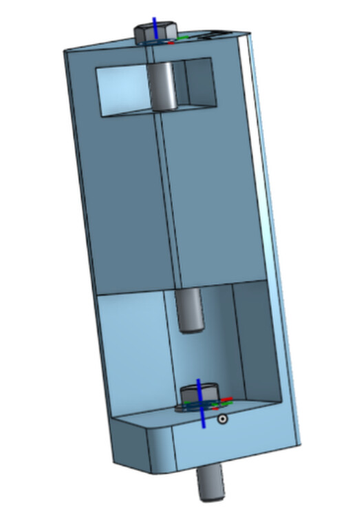
something like this (this has the height to the bottom arm at 70mm with an 18mm base, which is about right for a 3/4 spoilboard and 3/4 workpiece) this is a 4.5” bolt on top (no nut needed)
Can you post the dimensions for each cutout. I would like to manufacture using aluminum stock. I believe the 3d parts will have too much flex. tried to get the dimension from onshape with no success.
Can you post the dimensions for each cutout. I would like to manufacture using
aluminum stock. I believe the 3d parts will have too much flex.
the part can be made bigger as needed (and if it’s not stiff enough in practice,
I can put holes in it to put bolts in)
tried to get the dimension from onshape with no success.
the top of the bottom opening is height-of-bottom-arm - 5mm + (thickness-of-arm
thicness-of-anchor)/2
the other arms are:
height-of-bottom-arm + (thickness-of-arm - thicness-of-anchor)/2 +
thickness-of-arm * arm count
I give the anchor pockets 6mm of clearance from the edge of the hole
for the anchor nut, it’s a 20mm radius
note that all free designs in onshape can be cloned by anyone, and then you can
go in and look at the sketch (sketch 1 in this case) and see the dimensions I
set there
I cleaned up the model and set the default sizes a bit more sanely (including assuming 3/4” allowance for workpiece/spoilboard)
I also added a feature that if you give it your layer height it will try to use bridging to be able to print without support.
If I were to do a version of this in aluminum, I would not carve it out of a solid block, I would get a good size angle (say 3” or so) and cut three plates that fit inside the angle and have a hole in the same place, then weld them inside the angle, one at the bottom, the other two at varying heights spaced appropriately for each anchor
I’d go with extending the wall out, but maybe making that area lower infill via designed voids and print at 100% infill, based on what I’ve learned over the last year. Can’t trust various printer/slicers to do infill consistently, or for people to all choose good infill and wall thicknesses. Would also reduce chances for retraction issues at vertical edges from seam alignment if none of them came to sharp corners, especially under overhangs at the top of those slots.
Ok, tweaking the parameters to be a bit larger/thicker, here is a good set
(120mm long wedge, 4mm shell)
I print in PETG rather than PLA as I’m in Phoenix AZ and PLA just doesn’t survive outside of air conditioning here in the summer
print these solid, I do it with lots of perimeters, but 100% infill should work. There are ribs and voids built in to the model.
These are setup for 75mm from the ground to the lowest arm (configurable in onshape) so if you are using thin wasteboards, you may have to put a couple layers on top of each other to keep the anchor from pulling up on the arm during calibration (when cutting, your bit will mean the router is higher)
Even though these are setup to step up each anchor, if your ground isn’t level, your Z offset to each arm will be different. But with the belts almost level, any error will have less effect than with the Z offset being larger.
@wouldchuck you can use these, or we can change the ‘height of lowest arm’ value to something different and export them for inclusion in the repo. for things like this (and things defined in abundance) we should figure out a way to have a link to the onshape/abundance doc as well as a CAD export.
Cool. Yes I think the repo can have useful full cad files but also readmes with links to the editable parametric designs. For abundance we should be able to upload a text file that is the full code for the object as a back up. They are not very big. But since abundance lives in GitHub it seems like it might be more durable. Onshape could chang access or code at some point but abundance is forkable. I am finding that individual abundance docs are not very stable they change every time you.work with them but linking to a stable copy should be fine.
In terms of archiving Links decay but if someone can still have the STL or step at least they would have something usable to work from.
In terms of archiving Links decay but if someone can still have the STL or step at least they would have something usable to work from.
I agree both are good. The question with parameterized designs is figuring out
what version to export
Onshape will go away some time in the future, as will github. It’s too early in
the life of abundance to go in and make it work with other git repo systems
(including git on the local filesystem) but as it solidifies, it will get
better.
in onshape, it is possible to fork a specific version and link to that version,
but then you miss out on improvments.