Sorry, I have tried searching the forums but a month or two ago I remember seeing some 3d printed spacers for mounting the belts to a concrete floor so that the belts at the anchor match the belts on the machine, making the z offset zero. Does anyone know where those are?
I think you’re referring to the following post…
I am currently making my own version of this. I can post the stp files on here if it is successful
1 Like
Yes, that’s the one I was looking for. Thanks!
Now that I’m reading that other thread, I realize he never posted the files. did he send you a copy or could you send me a copy of your version? I really need the 1.75" work surface height.
Could you get the height clearance needed using existing Maslow corner anchors mounted to a stacked plywood block e.g. pyramid or tapered cylinder resistant to belt forces pulling inwards (CNC cut layers screwed and/or glued together with titebond or something), or, a simple 2" x 4" wood block with 4" or 5" bolt going through to concrete inserts recessed into garage slab? Thread bolts deep enough into concrete inserts to minimize overall slop.
Aza’s Built wrote:
Could you get the height clearance needed using existing Maslow corner anchors
mounted to a stacked plywood block (CNC cut) or 2" x 4" wood block with 4" or
5" bolt going through to concrete inserts recessed into garage slab?
Yes, there is nothing special about any of the anchor designs. you just need the
end of the belt to be able to bivot without moving up and down.
David Lang
1 Like
This is the way I would do it if I did not have a 3D printer.
- Drill 4 holes 1/2" diameter each for the 3/8" threaded drop in anchors
- Get 3/8" threaded rod and cut 4 sections 6-7" long
- Cut wood blocks of various thickness and drill a 3/8" hole in the center
- Thread the rods in each anchor
- Stack the wood to the desired offset
- Put end of belt over each anchor and secure with washer and nut.
With that being said, if you have a 3D printer, you can 3D print disks of various heights with a 3/8" hole in the center that you could stack to the desired height instead of using wood.
If anyone is interested in STL files for the disks I can post them if you give me the dimensions that you would like.
Here is a simple disk one is 3 inches in diameter, 1 inch high, and has a 3/8" hole and the other is 1.75 inches high
https://www.thingiverse.com/thing:7079558
Let me know if you would like other sizes. I can also play with different shapes as well.
I just posted a link to stl files, one is 1 inch high and the other is 1.75, let me know if you need a different size or shape and I will see what I can do.
Clinton Hull wrote:
This is the way I would do it if I did not have a 3D printer.
- Drill 4 holes 1/2" diameter each for the 3/8" threaded drop in anchors
- Get 3/8" threaded rod and cut 4 sections 6-7" long
- Cut wood blocks of various thickness and drill a 3/8" hole in the center
- Thread the rods in each anchor
- Stack the wood to the desired offset
- Put end of belt over each anchor and secure with washer and nut.
I would put a washer and nut below each anchor and tighten it, and then have a
nylock nut over the anchor that you bring close, but still allow the anchor to
pivot
you want the stack pulled tight to the floor to prevent any flexing.
David Lang
I am getting ready to test using aluminum stock for this. I tried 3d printed risers, but they just weren’t quite rigid enough. Unfortunately on the first test run with the aluminum risers one of my belts snapped, so I have some repair work to do before I can resume my testing.
1 Like
Kyle Burns wrote:
I am getting ready to test using aluminum stock for this. I tried 3d printed
risers, but they just weren’t quite rigid enough. Unfortunately on the first
test run with the aluminum risers one of my belts snapped, so I have some
repair work to do before I can resume my testing.
be it wood, plastic, or metal, you want wide, not narrow supports.
you are setting up a triangle of force, one corner being the base of the rod
where it is in the fllor, the second being the rod as it exits the top of the
riser, and the third is the outer edge of the riser on the floor.
you are trying to make this triangle not flex.
this means that the distance from the outer edge of the riser to the rod at the
floor cannot shift (needs to be a tight fit on the rod)
this means that the rod cannot move in relation to the top of the riser, either
horizontally or vertically.
and only after you have those settled do you need to think about the compressive
strength of the riser to resist the compression of the rod trying to bend
towards the outer bottom edge.
so make the riser as close a fit to the rod as you can, and have it be as fat as
poosible to give you a better angle to this triangle.
David Lang
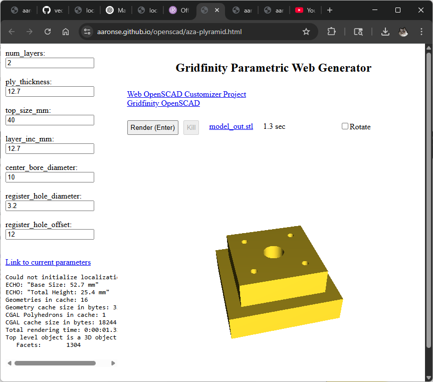
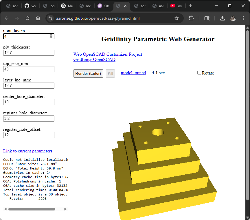
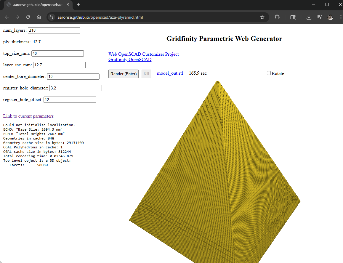
This is rough and quickly thrown together, but, thoughts on something like a web configurable Plyramid ™ corner mounts ![]() …
…
https://aaronse.github.io/openscad/aza-plyramid.html … (![]() Takes a while to load since the page uses OpenScad compiled to WASM ~7.5mb).
Takes a while to load since the page uses OpenScad compiled to WASM ~7.5mb).
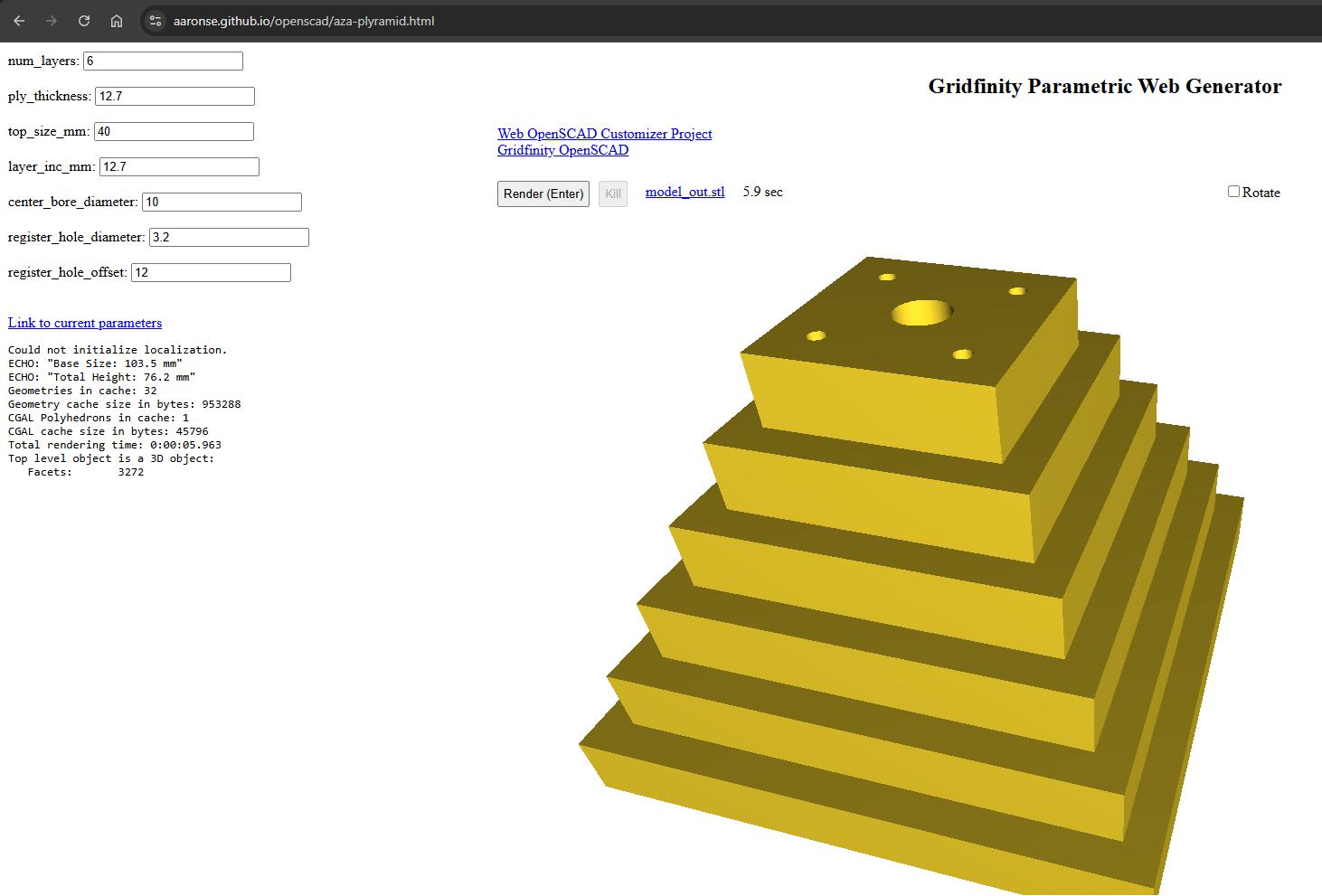
Configure whatever num_layers and ply_thickness makes sense for the overall desired height, and material thickness you’re working with…
Ideally, the page would let you render and download .dxf containing each layer, bonus points for automatically tiling shapes ready to CNC. GCode generation would be great too, but, one step at a time…
To minimize slop/pivoting on my uneven sloped garage slab, would likely supplement the Plyramids with wood shims, 3D-printed and/or wedge tiling shims.
1 Like
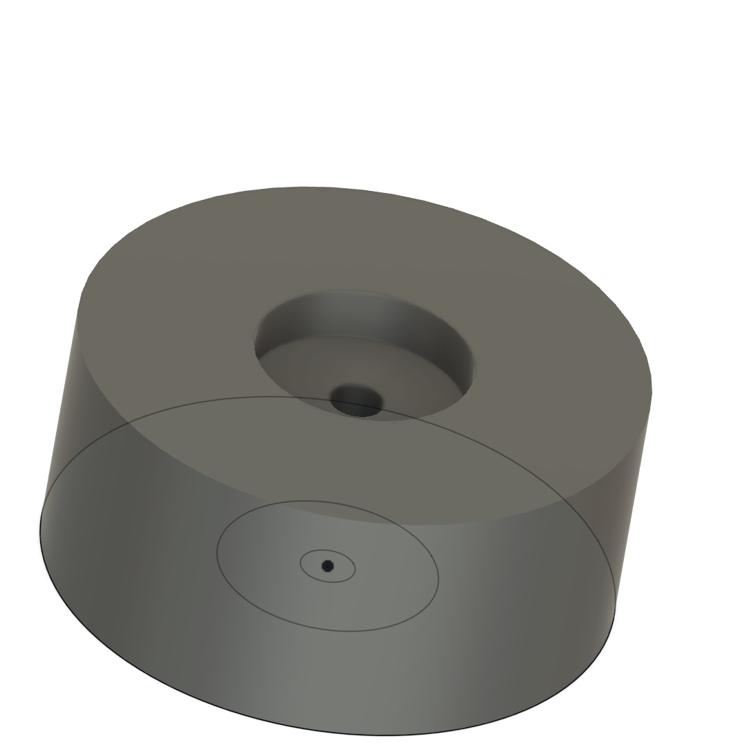
What about this one? It is about 4 inches in diameter and 1.75 inches tall. You would start with the treaded rod in the anchor. Next would come the riser, followed by a fender washer then a nut. You would tighten this down to establish a firm base. I would then add another fender washer or two followed by the corner anchor and then another nut.
This would allow you have a firm elevated base but at the same time allow some movement of the corner anchor. I can post to Thingiverse if anyone is interested.
2 Likes
Updated https://aaronse.github.io/openscad/aza-plyramid.html , cleaned up and made downloading SVG or DXF templates easier. Tested that generated files can be used in EstlCam to create tabbed parts. Let me know if you want details on how to do this.
Page is slow to load and render on mobile (tested on Android), so added frivolous animated Maslow 4 themed progress spinner, with Plyramid anchors for meta points.
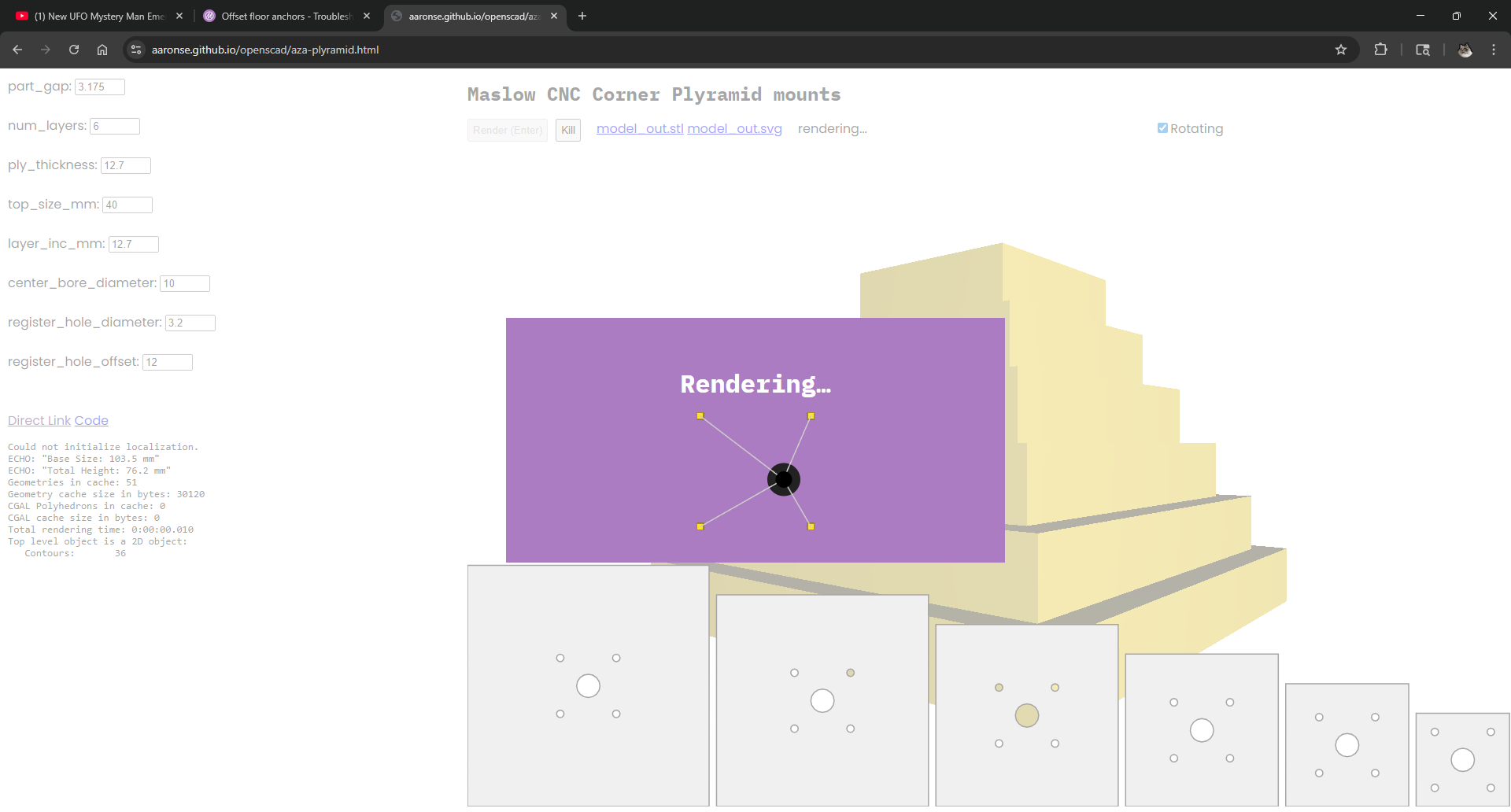
Click/Tap on the template to download the .SVG file. There’s a link too, but that can be hard to see/tap on mobile.
Happy 4th !
1 Like