I’ve cut some rough, warped plywood before on an 2.5mx3.5m wooden frame and things went OK. Encoder issues with static, not great cuts, but OK.
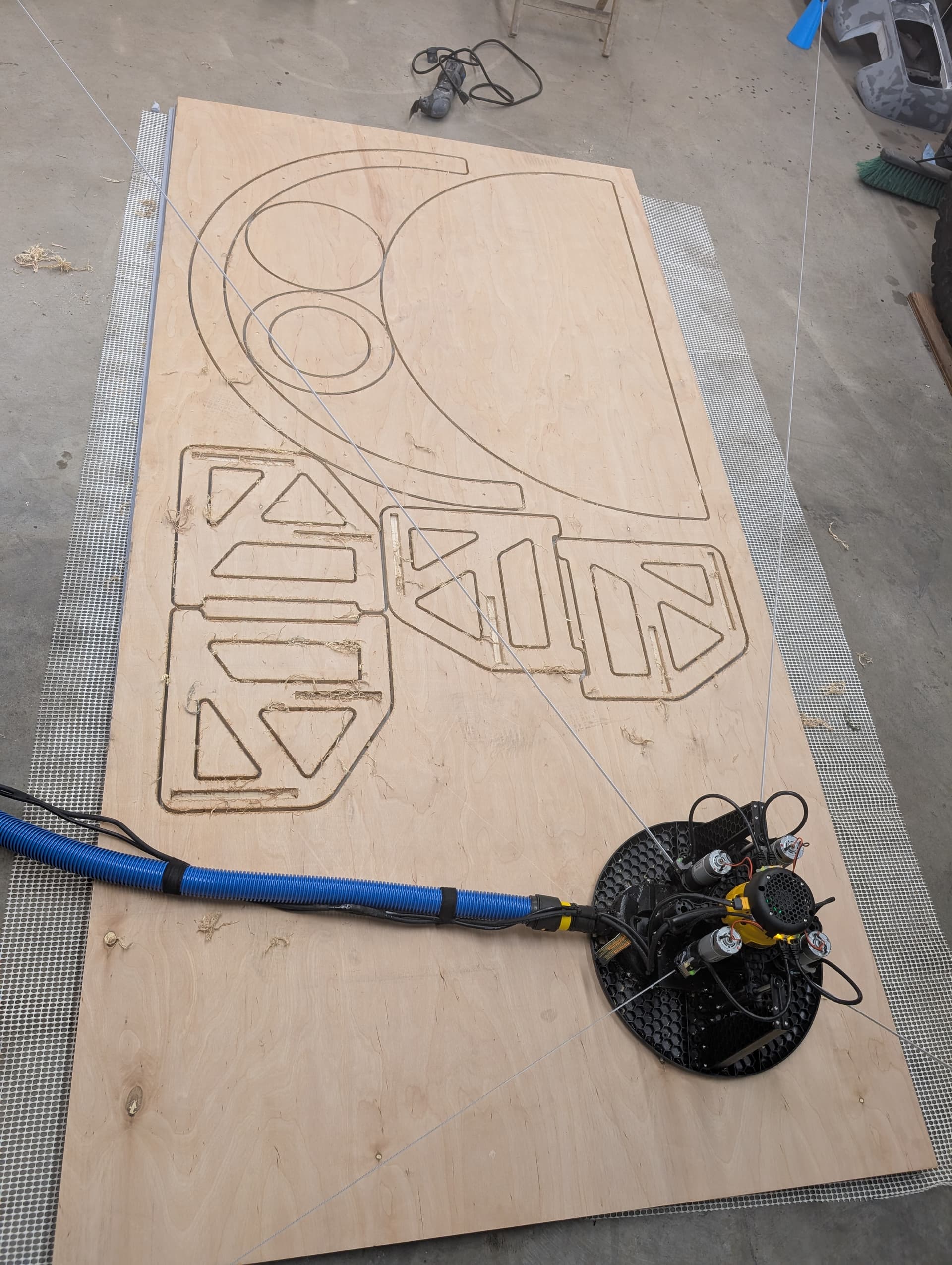
Then today I tried my new setup, concrete anchors at 3mx4m with standoffs for flat belts. Smooth ply. Anti static hose. And it just worked.
Calibration 9x9 2mx1m worked but fitness was just 0.5. Seemed to measure Y 30mm too high and X 30mm too narrow. Belt tension good across the whole work area.
I haven’t checked the dimensions of the parts yet, but it cut so nicely without a single hiccup.
This machine is awesome and as the bugs are worked out, will be even better. Everyone who’s been involved in bringing it to life should be proud. Cutting a 4x8 sheet, barely supervised, then packing the whole machine into a tote is just amazing.
I put 3/8 concrete anchors in the floor, then bought a 5, 6, 7 and 8" bolt. Drew up these parts 22mm difference in opening height for each arm and 1" taller for each bolt length. They’re configured for 1.75" of spoil board and plywood combined. Used 1kg of PLA to print the blue bits, and ABS for the knobs. Only have about 3 turns of thread engaged to make winding them in and out quicker. Quite specific to my setup, but if the STL or a STEP or SLDPRT file is useful I can share them.
I took some measurements of the biggest part and it was a little wide in X, and a little short in Y, by approximately the same amount my calibration mis-measured the anchor positions.
If I manually update the YAML to the actual anchor positions, do we expect that to help with dimensional stretch? I will update the a newer firmware when I can find some time before my next cutting session as I know there is the skew-fudge-factor added in there now that should help get things more dialled.
If you’re open to sharing, I for sure would appreciate the STEP/STL files. At worst it would be something to study and work concepts into something unique to my setup.
I’ll dig out the files and figure out how to share them soon, bear with me!
I don’t think it has any impact being only 3 threads, it is still tight. I did see a tiny bit of flex in the tallest one but I don’t know the exact source of it. PLA is pretty stiff and I burned up a whole kg printing all four.
I put my part of the cut pile together today, came out nice. The spots either side of the tabs were burnt from the machine stopping to raise and lower the bit either side of the tab, I used krabzcam, I’ll have to see what I can change to prevent those witness marks in the future. The slots I cut to put the steps into the sides were quite undersized, so for any future tab/slot things I’ll do some testing first to dial in the fitment.
One happy toddler who can now get into more things that she shouldn’t be!
I put my part of the cut pile together today, came out nice. The spots either
side of the tabs were burnt from the machine stopping to raise and lower the
bit either side of the tab, I used krabzcam, I’ll have to see what I can
change to prevent those witness marks in the future.
some CAM software has the option to make the tabs be trapizoid rather than
squared off. this makes it so that the machine can ramp up rather than stopping.
There is an ‘Attack Method’ parameter for profiles in KrabzCAM which have a ‘ramp’-option.
It doesn’t exactly make the tabs trapizoidal, but it prevents vertical plunging motion after passing over a tab.
Like this:
I’m totally new to CNC so apologies if this isn’t relevant, also I’m based in the UK for context.
Manually when cutting any rebate or slot larger than the router bit I normally cut 1-2mm inside the line using multiple passes as necessary for the required depth, and then cut to the line in one pass at full depth, pulling the router back into free space after the cut, preventing the non-cutting contact burn.
A similar method is used for cutting post-formed worktop mason’s mitres - it allows the heavy plunging and waste removal work to be completed away from the finished edge, and a final light pass to provide the crisp edge.
This is particularly relevant when using long bits in jigs - they can deflect a surprising amount.
I presume a similar method could be scripted for the cutting path in CNC.
I’m fairly new as well, but am typically seeing what you describe here as a “roughing operation” or “roughing pass” followed by “finishing operation” or “finishing pass”. If you look for that terminology I think most CAM applications will present an option to include that behavior in the generated NC program.
Yeah that is something I ought to play with, Krabzcam does have that option (roughing clearance) but it’s a bit awkward as you have to re-configure the tabs for the new toolpath so if they don’t line up you might not have a tab left over. As great as Krabzcam is for casual stuff, I think I will explore more professional offerings when I get stuck into bigger projects.
@whoisdis, if possible could you send me a copy of those files? I have a similar setup, but my spool board + cutting surface is around 1.2". I am running into an issue where the belt from the lowest motor is contacting the board. I think a modified version of those standoffs would be perfect.