Squared cuts are not eaven sides areare not tje same sized for like 1/2 inch

Hi everybody and thanks for resd my post, thing i s that I am trying to cut some files from the examples on the comunity garden and after download the files ald sent an run the cut proces with the grown control software some cuts are not well performed they are not eaven on the sides.

For exaple if what I am cuting has rectangular shape the maslow cuts it a little bit like a romboide like title bit crucked. Hope you can help me.

Thanks in advance.

1 Like

Can you upload the cut-file and a picture of the cut?
If you are a to ‘fresh’ user a few likes and responses will get you over the spam protection.

Firmware and GroundControl version used is also great help.

1 Like

You also may find this page useful. Troubleshooting: Cutting Issues

Hi everybody,
newbie from Germany having a similar issue.
Frame dimensions are same as wooden frame recommended by MakerMade …
Calibration went smooth and easy …
We did some small test cuts, but all in the center area, with perfect results. And now this:


Anybody out there with some ideas as to why there is such a significant inaccuracy?

Can you tell us more about what happened? Is the issue those lines over to the right which don’t meet in the corners?

1 Like

Well, we see several issues! :frowning:

  1. When you see from left to right: the whole cut sags, but should be parallel to the edge of the board.
  2. the cuttings are not square! even the rectangle cut in the center, partly below the sledge is 2mm out of square. the “D” shape left meassures are about 1.2cm out of square.
  3. the rectangle on the right meassures are out of square similary.
  4. the “2 lines” are pockets and as well not parallel to each other …

I’ve stopped the cut to not waste any more material …

We are using the lastest firmware/GroundControl versions …

Let me give you a little insight on my initial experiences with my Maslow. Maybe this can help you, maybe I’m not even close to helping with your particular issue, but I think this may be of help.

When I first started, my circles were more like footballs, and my lines weren’t quite as parallel to the edges as they were designed to be in my CAD program. My first few cuts were basically wasting wood.

What solved my problem is, I went back through the calibration. But this time, I went really slow. I read every single thing 10 times before I did the step, and 10 more times before I clicked next. Slowing down, and really putting 100% effort into the calibration, my machine started cutting as it was supposed to. And within 1/16" accuracy.

So my advice, REALLY go though the calibration and treat it like it’s brain surgery. Because it is the most important part of the machine.

If that doesn’t work, check for flexing of your top bar.

Hope some of this is useful to your situation, and don’t worry, there are TONS of great people on here with the knowledge to help you get through this!

thanks for your advise … We did the calibaration procedure very slow and much more, we did it 3 times in a row to make sure that all parameters such as distance of the motors etc. are the same.

Furthermore we did some, we called it, test cuts, which have been some parametric chairs


(https://www.etsy.com/de/listing/694399823/parametrische-stuhl-cnc-inneneinrichtung?ref=yr_purchases)

Last but not least, our frame is a steel frame. hence I doubt the top bar is flexing …

Today we do some frame modifications, as we are expecting the metal maslow upgrade kit to arrive and we’ll do another 3-pass calibration procedure.

One question and as you have mentioned 1/16" accuracy, which translates to 1.59 mm: Can you please describe this “tolerance” a bit more? i.e. is it over the full length of the working area?

2 Likes

You’re going to love that metal sled! I just got one a couple weeks ago and it’s been great! Loving that z-axis movement! So fast and fluid.

As far as the tolerance, I want to say it’s mostly across the board, I did some spot checking yesterday and my cuts were spaced out over a full sheet. The measurements were very spot on to what my CAD measurements were. I’ll show you to give you an example…

There is only 6" space around the entire board. I made the model to utilize as much of 1 full board as I could without getting into the trouble areas. Which, I did anyway lol In the lower right corner, my machine hates it down there. But all of those pieces measured out to what my CAD measurements were, the smaller pieces, were only 1/16" off. Luckily it was 1/16" larger, so I can just sand it down to size.

1 Like

Awesome!

I just checked the meassurements for the “D” shape on the picture above and below and compared it with the design file.

Here are the results:

There’s a big discrepancy between the designed 530mm and the result 507 mm respectively 516 mm. This is an inaccuracy of 23mm and 14mm!!!

Same for the 78 mm and 67 mm, which should be 75 mm…

Maybe this discribes the problem a little more in detail?

Here’s the g-code, in case this helps for the findings: Pilates-Chair - Details - Teil I - Kopie.nc (24.6 KB)

I am fairly certain that something is going very wrong in the calibration process. That distortion pattern you are seeing where a straight line from one side of the sheet to the other bends up is a classic symptom of something being off in the calibration process.

Check out the simulator under advanced options in Ground Control, it’s a fun way to play around with adding distortion to different measurements and seeing how the affect the cut.

The first place I would look to fix the issue is to measure by hand and make sure that the measurements for the distance between the motors and the ring size shown in the settings match up with what you are seeing in real life. Those two measurements are the critical ones. If either one is off you will get the sort of distortion you are seeing.

Hey folks!
I spent almost the total day today to calibrate my Maslow. Unfortunatelly to no avail …

Some facts upfront:
We build a steel frame with a lenght of the top bar being 3000mm.
Center of sprocket is equally 26mm from the left respectively right edge of the top bar.
Hence, this means that the distance between motors must be something around 2948mm. Am I right?

However, first I’ve tried to do the calibration using our RasperryPi. But this was always “hanging” after the third step of the procedure, so I connected my Macbook, which was running fine.

By the way, the RasberryPi reported a version mismatch of GC Version 1.28 and FW version 1.26. The Mac has GC 1.26.

In total I did 14 calibrations, but none results with the same distance of motors!!!
Furthermore, I had to reset the Arduino after 4 runs, it simply didn’t respond.
Below all results incl. screenshots!

Does anybody have a clou whats going wrong here in good old Germany?

The first calibration meassured the motor distance being 2912.66mm:


The second calibration meassured the motor distance being 2925.59mm:

The third calibration meassured the motor distance being 2944.91mm:

The fourth calibration meassured the motor distance being 2944.55mm:

The fifth calibration meassured the motor distance being 2944.33mm:

The sixth calibration meassured the motor distance being 2944.23mm:

The seventh calibration meassured the motor distance being 2938.13mm:

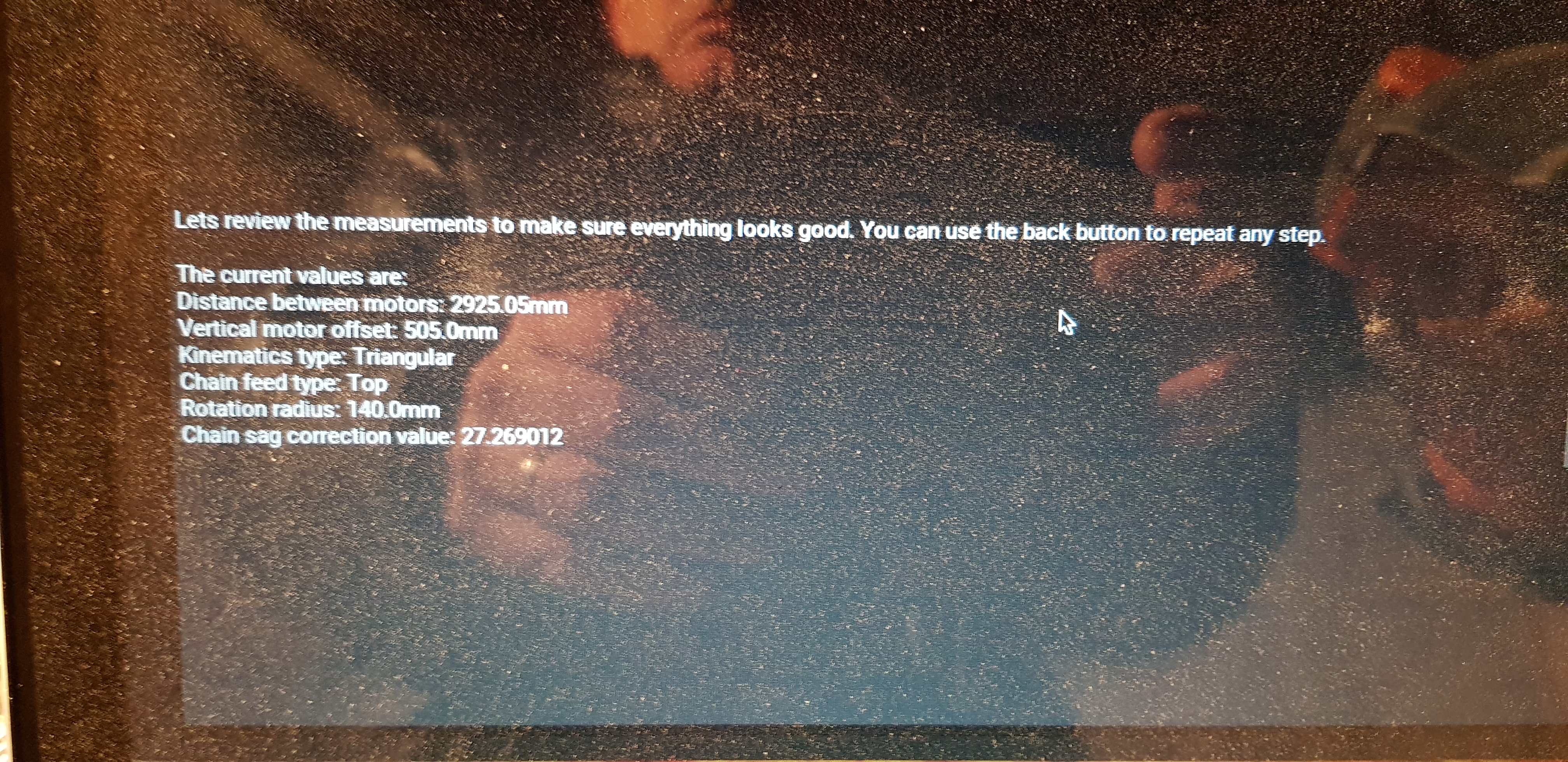
The eight calibration meassured the motor distance being 2925.05mm:

The ninth calibration meassured the motor distance being 2944.25mm:

The tenth calibration meassured the motor distance being 2943.63mm:

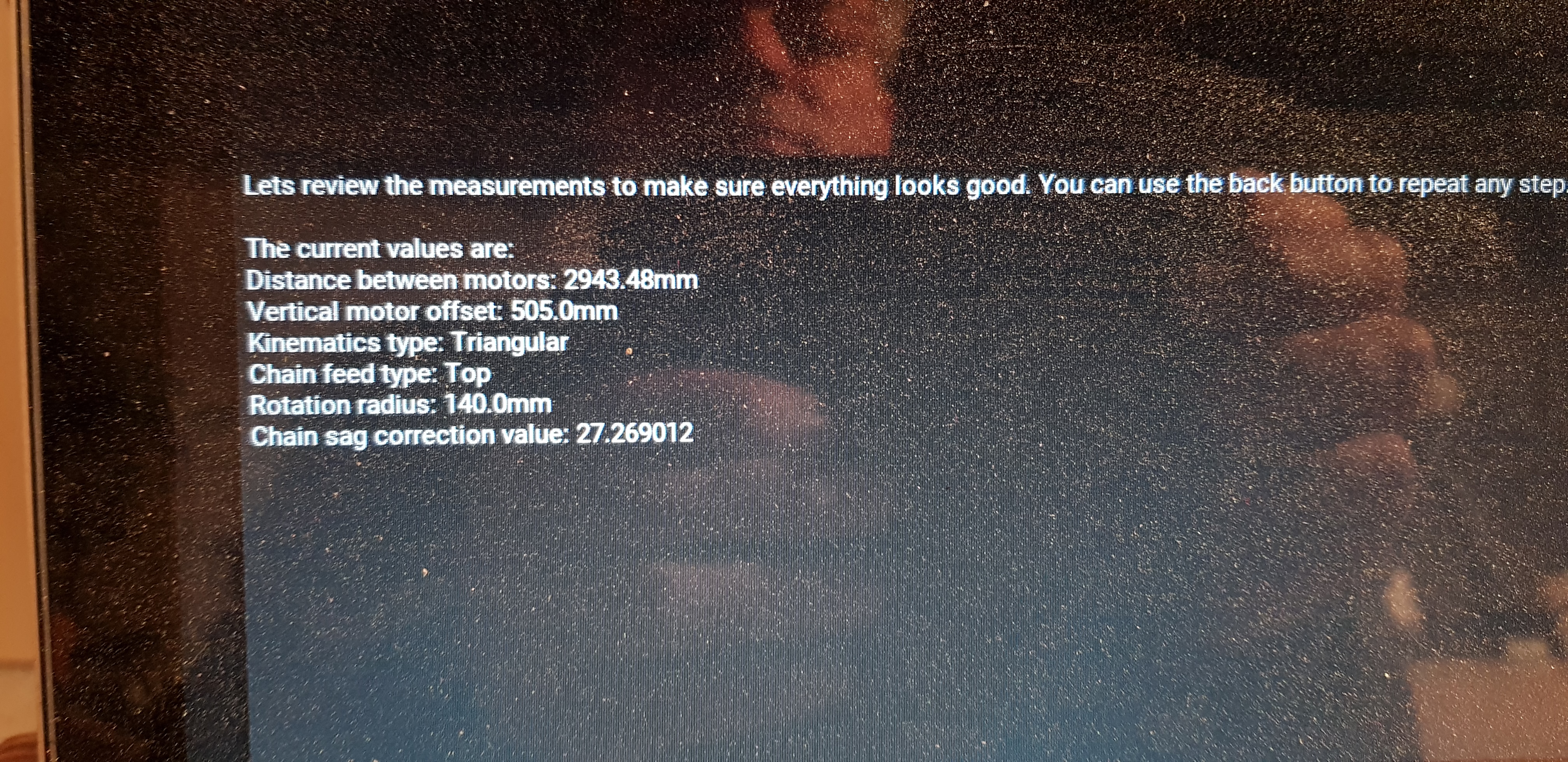
The eleventh calibration meassured the motor distance being 2943.48mm:

I did several more!
The twelfth calibration meassured the motor distance being 2937.15mm.
The thirteenth calibration meassured the motor distance being 2943.87mm.
The fourteenth calibration meassured the motor distance being 2936.6mm.

1 Like

When you say you did the calibration multiple times, did you do the ‘full’ calibration where you measured the distance between motors by stretching the chain across the motors?

Well, I’ll answer my own question since you must have since the distance between motors is not optimized during calibration.

I’m not a fan of ground control’s method of measuring distance between motors. I never could get consistent (or accurate) results. I suggest that if you know the exact value between the two motors (2948 mm) go to Settings and enter that value. When you go to calibrate, press the skip button when it wants you to measure the distance between motors. It will use the value from settings.

2 Likes

OK! My assumption distance between motors is meassured between center of sprockets is correct?

1 Like

Yes. Center of sprocket to center of sprocket.

1 Like

I think that sounds like the issue for sure. Those numbers should be the same to within a fraction of a mm. It worries me that they aren’t, as in possibly something else is going on…potentially a loose connector.

I agree with @madgrizzle that the right course of action is to use the number you know to be right, but let’s not forget that something could be up with that measurement not coming out accurate.

1 Like

OK, will give it a try tomorrow … to cold in the garage now :slight_smile:
and to answer your question: I did the full calibration until the summary screen and restarted once I’'ve noticed the inconsistancy …

1 Like

You should get an award for that :wink:

1 Like

@bar … thats why I went multiple times … Some results are at least in the same neighborhood … but some are off center … If I can be of assistance to figure out whats wrong I’m happy to help … just let me know what to do!

1 Like