Here are the results of a cutting test.
Does anyone have any suggestions regarding the discrepancies observed and how to improve the cutting precision?
I note:
Good point: my up/down bit makes a very clean cut in the plywood! (6mm cutter)
the circles are not round
the dog bone cuts are surprisingly asymmetrical…
the straight lines are not perfectly straight
my piece is supposed to be 200 mm x 100 mm, but in reality it is 198 x 98 mm
And the input data:
Feed rate of 900 mm/min
Router rotation at minimum (speed 1)
7.5 mm pass (recommended by the bit supplier)
10% ramps
Modeling in Fusion and machine settings in Estlcam
Cutting 10 mm plywood
cutting in vertical position
9x9 calibration on a 2000x1000mm surface
Observations during cutting: quite noisy, some vibration but small, fairly clean chips. By increasing the router rotation speed, it seems that my chips are too small.
Well, I tried several rotation speeds, but it doesn’t make much difference.
I recalibrated (with difficulty…).
My circles are still not round and the dog bones are asymmetrical…
My cuts overlap almost perfectly, so there is good precision/repeatability. However, the accuracy is very poor…
I’m starting to think that this is the natural limit of the machine and that I shouldn’t expect anything better…
One thing I don’t understand is why the two bottom belts don’t tighten when operating vertically. The machine isn’t very rigid to begin with, so with these two belts not tightened, it’s even worse!
I’m a little disappointed at the moment… it’s difficult to imagine assembling objects with these inaccuracies.
And that’s not to mention the machine’s mediocre reliability. The number of times it crashes during calibration, setup, and while executing a Gcode, as well as the sluggishness of execution (it takes
I’m a little disappointed at the moment… it’s difficult to imagine assembling objects with such inaccuracies.
And that’s not to mention the machine’s mediocre reliability. The number of times it crashes during calibration, startup, while executing a Gcode, etc.
And each time it’s such a hassle to get it back up and running: putting the belts in, then taking them out…
Even though I noticed that the latest firmware recorded the machine’s position…
In short, I’m disappointed with this machine… I’m starting to lose patience and I think it’s going to gather dust in a corner…
One thing I don¢t understand is why the two bottom belts don¢t tighten when
operating vertically. The machine isn¢t very rigid to begin with, so with
these two belts not tightened, it¢s even worse!
If the belts are not tight when cutting, then the machine’s idea of where the
anchors are is wrong. This is what calibration does.
until this is fixed, no other efforts will give you accurate cuts.
what size frame do you have? what size calibration grid are you using?
One thing I don’t understand is why the two bottom belts don’t tighten when
operating vertically. The machine isn’t very rigid to begin with, so with
these two belts not tightened, it’s even worse!
If the belts are not tight when cutting, then the machine’s idea of where the
anchors are is wrong. This is what calibration does.
until this is fixed, no other efforts will give you accurate cuts.
what size frame do you have? what size calibration grid are you using?
are the belts pulling tight at each measurement location during calibration?
No errors, the belts remain taut at each point measurement (however, the two bottom belts slacken when the machine moves)
Then I try a test cut… I plunge the bit into the wood while adjusting the Z (following a display bug, an endless number appeared on the screen and the Z dropped to that value → forcing the stepper motors…)
I restart the machine, reset the Z to the correct value, insert the belts and then remove them (again, again, again…), press the belt tension button, and the lower left belt won’t move (this has happened several times today).
There is the size of your frame (distance between anchors) and the grid area the
calibration covers.
Another thing that could be hurting is the Z offsets, where do your anchors
attach to the frame compared to the bottom of the sled when you do the
calibration?
The height of the anchors relative to the sled plays a significant role. This will determine how much the belt will extend with each movement, and the anchors must rotate freely. Calibration is also necessary without a cutter and with the Z axis touching the bottom. Sometimes it’s necessary to smooth the reels so the belt can exit freely. It may happen that during assembly, when tightening the screws, the reel bulges and slows down. When moving it, it doesn’t reach the speed of the other reels. There’s something to check: many of us have made the mistake of not configuring the menu vertically, as it’s horizontal by default.
I put the fasteners as low as possible on the anchors and they don’t move. Sometimes, as a precaution, I add a nut, but it’s not very useful…
the ends of the belt do need to rotate on the bolts.
the distance from the anchors to the arms does matter.
If you were doing this on concrete, and have the ends of the belts against the
concrete, then you have a wasteboard sitting on the concrete, then your
workpiece sitting on top of the wasteboard, then your sled on top of the
workpiece, you need to tell the maslow about those extra distances.
Okay, I understand the limitations regarding frame size better now. This tool makes it quite clear.
As for the height of the anchors, I didn’t think it would have a significant impact given the length of the straps (very slight angle relative to the horizontal).
My strap ends are currently set to 0, i.e., under the sacrificial plate. In theory, this means that I could print spacers: one 12 mm thick (the thickness of my sacrificial plate) and the other the thickness of the plate I want to cut.
But I doubt the impact of this mathematically because:
Does the calibration calculation include the height of the machine’s arms? (4 different heights for the 4 arms)
When the machine is working, this height can also vary by several millimeters (normally to the maximum thickness of the plate to be cut…)
Okay, I understand the limitations regarding frame size better now. This tool makes it quite clear.
As for the height of the anchors, I didn’t think it would have a significant
impact given the length of the straps (very slight angle relative to the
horizontal).
it matters more on the higher arms and more the closer you get to the anchors
My strap ends are currently set to 0, i.e., under the sacrificial plate. In
theory, this means that I could print spacers: one 12 mm thick (the thickness
of my sacrificial plate) and the other the thickness of the plate I want to
cut.
you could. the closer to level the belts are, the less friction there will be
and the less any height difference will matter. but you need to make sure that
the anchors don’t flex.
But I doubt the impact of this mathematically because:
Does the calibration calculation include the height of the machine’s arms? (4 different heights for the 4 arms)
yes. There is a Z coordinate for each anchor as well as an x/y coordinate.
When the machine is working, this height can also vary by several millimeters (normally to the maximum thickness of the plate to be cut…)
yes
This is why we have a workpiece thickness setting and a wasteboard setting.
There is disagreement as to how much it matters, but when things aren’t working
(like in your case), it’s one thing to try. Some people have reported that it
has been the difference for them.
If your anchors are at the back of the wasteboard, then I would suggest adding
the wasteboard thickness (it’s in settings, not directly exposed in the UI,
there is disagreement about how much it matters)
the original frame design had the anchors at the same height as the top of the
wasteboard.
New calibration with recommended settings. Firmware 1.13.
Test file → a circular pocket with a diameter of 10mm / depth of 5mm in a disc with a diameter of 15mm. Cut out of 10mm plywood
Small circles are sort of the Maslow 4’s achilies heel.
This is likely more due to the machine rocking as the forces switch directions as it goes around in a small circle than it is due to calibration issues.
Calibration issues would manafest in a large part.
It improve these try using a shorter router bit to make it so the machine is operating lower down where it is more rigid and try cutting with shallower passes more slowly.
making the bottom of the sled slipperyier could help
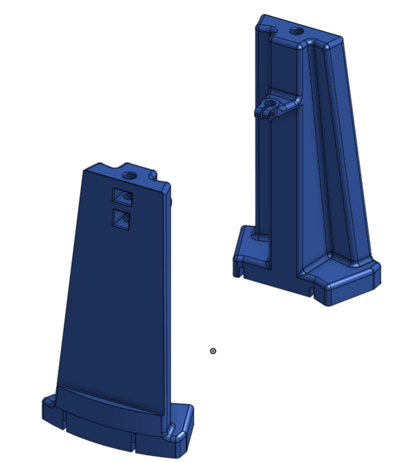
I’m planning to try and print these supports over the next couple of days to give the rods more support (the stock ones are great in terms of resisting movement radial from the bit, but the combination of injection molding draft, thin ears, and a fairly narrow base mean they don’t help much in the circular direction around the bit)
I have these as one piece and two piece options, I’ll be printing the one piece version (the reason these extend above the rod clamps is to give a good way to attach a handle or mount electronics, the flat outside is so that I can mount the power supply to the sled and only have one power cable rather than two)