Yes, if the motor/encoder test is failing, you need to fix that first.
David Lang
Yes, if the motor/encoder test is failing, you need to fix that first.
David Lang
So will a one sensor motor work with the Maslow? I bought this one thinking it would work as I saw that @clintloggins had posted it worked for him.
I’ve done the standard trouble shooting. I did hook up and extra x/y axis motor that I have and it passes the encoder text on the z-axis cable. Is there another setting Maslow that would change it from a dual-hall sensor to single?
the maslow needs a quad encoder motor, but if it has an A/B channel, that should
work (the one in the amazon link above should work)
are you sure you have both power and ground for the hall sensors hooked up?
without power the hall sensors won’t work.
David Lang
Sorry @jbreezy just getting on the forum for the weekend. It definitely sounds like a wiring issue. I recall the misdirection happening to me. Will look back through my dm as I think I have a digram. Not certain it will help since I made my own cables but you may be able to figure out.
Hi Jatt
I just had a quick look to the A1233 ic datasheet, and it seems to have an 'embedded logic’ quadrature encoder .
Although it senses direction, its output signals are encoded different and will not work with the current firmware, the K package version of the A1233 only outputs direction and speed.
Either way, if it is an US5881LUA or the A1233, the Maslow firmware will not decode them correctly.
Sorry for late reply, I was out of town last weekend 
A one single channel sensor encoder can be effectively used, we can energize a dc motor and then count the steps to know how much it moved (also how fast), then we can reverse the polarity and count steps again to know how far it moved in the opposite direction, although we know the direction and movement, this encoder does not sense direction at all, this is done at a logic level, we control the polarity (direction) and then just count the steps.
Unfortunately, this is not how the Maslow firmware works, It is expecting two channel hi/low 90 degree offset signals to decode (cuadrature encoder).
In order for it to have an A and B out, it must have a quadrature output. There are 2 hall effect sensors in one ic. They are 90° out of phase with each other. The actual location on the pcb doesn’t matter at all, as long as the signals are 90° out of phase. See the oscilloscope trace on the polulu page to see that the signals are in fact 90° out pf phase with each other.
I just showed the A1233 as an example of a dual hall effect sensor. There are several more of them. The MT-1451 comes to mind as an AB quadrature output dual channel hall sensor in the correct package for this board.
The maslow should understand any hall effect sensor that uses AB phase out, as the motors that use the YC2010-28 encoder board are. Thus this motor should work with the maslow. However, as he had the wiring hooked up backwards (positive and negative reversed), the hall effect sensors are probably toast. They don’t have polarity protection, and hooking them up backwards tends to fry them.
I get it, we are just guessing about what encoder it actually has, but is not uncommon to see encoders with a single channel sensor, and that’s why I thought this could be the problem, I’m just trying to help.
In the case of the A1233 you are right, it’s a single ic with two sensors and a “Internal logic circuitry” that ‘generates’ the offset, but in the case of a single sensor as the US5881LUA, the position around the magnetic wheel is what gives the 90 degrees phase offset.
Quadrature has nothing to do with generating the output, it is how you read/decode it.
The encoder has to have A & B channels first, then you can read it any way you want (rising/falling edge for quadrature), in the case of the Arduino, you can use an interrupt and combine the two waves in to one to double the pulses, increasing the sensitivity of the motor position.
I agree
Is no doubt in my mind that the problem is the encoder, either is toasted or is not the right one.
Thanks for all the feedback here. I’ve been out of town for the past few days so now I’m back at it. I’m going to try and order a new motor to see if I did in fact fry the encoder. I have verified all my connections ant they are solid so I will get back with you all once I get the new motor in.
Hello, I hope this might help? I had the same problem and I read somewhere on the settings page you need to either add a minus sign or remove it from the 3.47 z axis. That seemed to work.
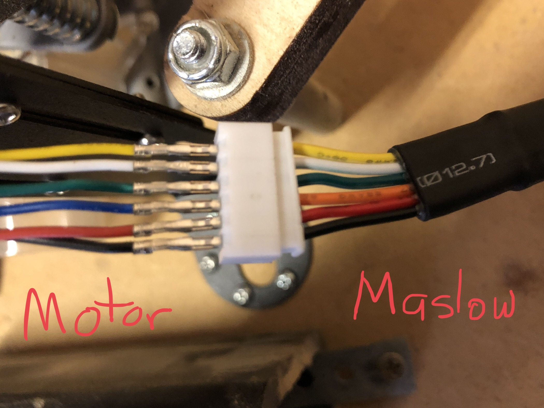
OK, I figured it out (partially with the help from The Blue Smoke Herder Shield - AKA the New Maslow Shield (TLE5206) - #251 by dlang thread). The wiring schematic from Amazon is not correct. Here is a picture of how mine is now hooked up.
According to the Amazon:
Pin 1: M+ (Red)
Pin 2: M- (Blk)
Pin 3: HS GND (Green)
Pin 4: HS Vcc (Blu)
Pin 5: HS A Vout (Yellow)
Pin 6: HS B Vout (White)
Maslow (Entom Motor):
Pin 1: M- (Blk)
Pin 2: M+ (Red)
Pin 3: HS Vcc (Orange)
Pin 4: HS GND (Green)
Pin 5: HS A Vout (White)
Pin 6: HS B Vout (Yellow)
So, one would think, hey, Pins 3&4 and pins 5&6 need to be switched in order to work. NOT THE CASE!!! If you match up the wire colors (with the exception of orange and blue) everything works perfectly.
For educational purposes here:
If you hook up the motor based on the pin layout given in the diagrams, the motor moves back and forth (constantly reversing regardless of command input).
If you switch pins 3&4 the motor will move the direction you tell it to but you cant control how far it moves and the Maslow does not read any movement.
If you switch 3&4 and 5&6, then you are happy as a clam, everything works right, the colors all match and you can thank to Malsow community for helping out!
As a side note: switching all these wires around in various configuration did not fry my encoder. 
Thank you guys for all your help, it is greatly appreciated.
Also, all three axis now pass the encoder test.
I’m glad you figure it out
Thank you for posting the correct wiring connections 
as a side note… please please please put heatshrink on those exposed metal connectors. if they touch and short out, bad things will happen to your maslow board.
You’re absolutely right, I just had it that way while I tested. Not smart. . . I know. . .
Thanks again for everyone’s help.
All the help you recieved and your hard work saved my bacon. See here:
Thanks!