12 ft. Top Bar, wall-mounted frame, Calibration issues

Hi all,

I’m new to Maslow CNC, and elected to go big with my frame in a fairly small space for the machine, and jumped straight to a 12 ft Top bar for my frame. Having barely a two-car garage and parking two vehicles in that garage, which is also packed with the various other things, I elected to wall-mount my frame instead of giving it a free floating frame and built it so it can stow vertically or deploy to the recommended angle for use. This all went fairly well and allows the machine to fit.

I purchased the kit from Maker Made including the Z motor and sled but didn’t spring for the upgraded version… at least not yet. I’m running the standard router. Controlling this via a Pi, I have skipped GroundControl entirely, and moved to WebControl. It took a few days, but I am able to get UP, DOWN, LEFT, RIGHT and Z movement. I’ve found center/home and have validated all of the parts are working.

I’m having an issue with calibration. I have a 1219.2mm spoil height, and a 2438.4 spoil width (4FTx8FT workspace). My motor width is 3552.825mm (12 ft top bar). My motor height is 832.2mm. I am feeding chains from the bottom.

I’m somewhat confused by the directions in the calibration process. I assume “setting zero” is just that, placing a single tooth on each motor straight up, and placing chain onto the motor so that the sled is centered, and manually setting home position, based on validating visually that the sled is in the right place. I don’t understand all of the “first link on chain” and feed “extend chains” nonsense I’m seeing as part of this process… why or what is that supposed to accomplish? Is it doing some mystical magic I’m not picking up on? If so, it may be feeding into my problem… which… I know this is a long way getting to my issue.

When I run the triangular calibration, it starts with motion lowering the sled several inches immediately, and after traversing left, it seems that the top/left cut is several inches lower than it should be, and if I let it continue, the lower cuts will drop my sled all the way off the spoil board… out of the work zone. I don’t understand why this is the case, because zero (X 0, Y 0) should be 609.6mm from the top of the spoil board and 1219mm from the left of the spoil board. If zeroed, I can’t understand why the initial downward movement occurs at all…

Someone send me a lifeline. Thanks in advance.
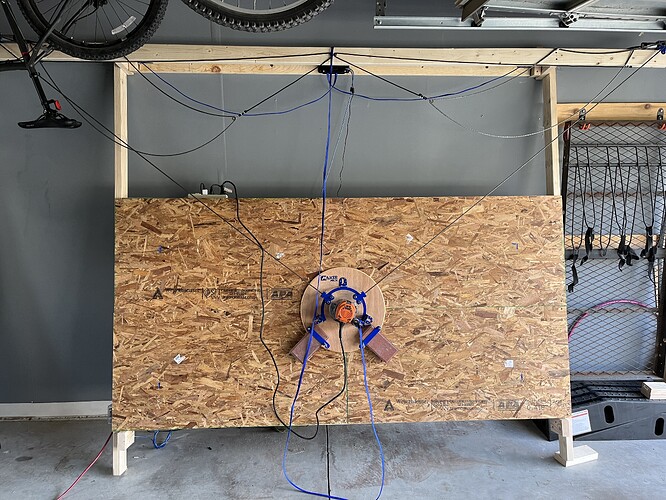
Extending the chains is what allows the machine to set itself and know where it actually is based on the amount of each chain released. What you are doing is basically telling the machine it where it thinks it is but you have manually placed it into another.

Placing a sprocket vertical and then extending, once done you are supposed to then mark which chain and spoke are vertical, and you use THAT to quickly reset the chains.

This is causing all of the machines X/Y movements to be incorrect.

When using a larger top bar, unless you compensate for the longer chains and distances by extending a larger amount of chain that is a multiple of the sprocket rotation, you sled WILL NOT be centered after a chain extend/reset. You have to manually figure out how much chain needs to be extended if you want you sled to be in the center after a chain reset.

With initial measurements entered and the chains extended properly and then hooked up to your sled pressing the home button will send the sled to the center of your workpiece.

Hope that was understandable and helps.

No… not really, maybe, I guess… it seems entirely backwards. If you “Set Zero” before you feed out chain, you’re not really setting zero…. I come from 3D printing where endstops essentially define zero, and you are only working off positive values… with this, feeding out chain on both sides after zero, means you don’t actually work from zero, “zero” is actually “negative x/y however-much chain you fed out”

more precisely, if you use the default extend distance, the two chains will not
get close enough together to hook to the sled.

let’s figure out how long

let’s make a right triangle with the center and a motor at the corners

with a 3550mm motor spacing this is a horizontal distance of ~1775mm
with a motor height of 832mm (is your top beam really 32" above the top of the
workpiece??) and anothe 2’ (~610mm) to the center of your 4x8 plywood you have a
vertical disance of ~1442mm

via a^2 + b^2 = c^2
c = ~2287mm

since this needs to be a multiple of 6.35mm (even number of links of the chain,
this is just over 360 links, so if you use 2286mm it will put you just a little
above the center

this number should then be fudged a little bit depending on the sled you are
using (how much distance gets added to the chain by the mount to the sled, in a
line directly to the center of the router bit, adjust this 2286mm so that you
still have a multiple of 6.35mm)

change the 1650/1651mm chain reset distance to this value in the settings.

then what you will do is get a tooth of the sprocket centerd vertially (I like
to put the chain on it with a small magnetic level on top of the chain and move
it till that’s elevel), then when you ‘extend the chain’ it will feed out 360
links of chain (minus the distance from the center of the sled (I believe, plus
a few more to account for wrapping around the sprocket)

you should have a tooth at the 12 o’clock position on both motors again if you
did this right.

you do this for the other chain as well, then hook your sled to both chains and
you will be close to the middle.

Mark the chain links that are straddling that 12 o’clock tooth (you don’t need
to mark the sprocket, any tooth being straight up is good enough)

when you need to reset the chains because the machine lost it’s position, you
will set each motor to have a tooth at the 12 o’clock position, put these marked
links there, tell it to reset the chains to a known distance, and it now knows
where it is.

you will then do your calibration. The reason for doing the calibration is that
these machines are very sensitive to the distances being slightly wrong. to fix
this, we have you do the calibration routine and the firmware gathers data to
generate some ‘fudge factors’ to correct the dimensions that you measured to get
the best cutting.

I think the holey calibration routine is better from a theoretical point of
view, but people have successfully used both types.

one thing that you will see is that after you do your calibration and return to
the center, you will no longer have a sprocket tooth exactly at the 12 o’clock
position. this means that when you do the chain reset, you are not going to be
quite as accurate as you are immediatly after feeding the chain out from
scratch.

An Idea that I have (untested) is to see how much you have to move the motors to
get them to a tooth being at 12 o’clock, and see if you can find a chain length
that gets both motors as close to being at 12 o’clock as possible, then change
your length to account for this and re-do the calibration with the new number to
see if this ends up being more accurate

When you are happy with the results, it’s good to mark this point (drilling a
hole with a 1/4" bit works well) to make it easier to get things close.

David Lang

0,0 is the center of the work area. If you have some gcode that you want to
offset from that, you move to where you would want that zero to be and ‘set
home’

but this has no impact on the true 0,0 of the machine, and you need to know that
true 0,0 as the angles change things a LOT compared to how a typical 3d printer
works (it’s more like a delta machine, if you don’t home the three positions of
a delta correctly, you don’t just have the results offset, you have the results
distorted)

David Lang

I’ll have to give this a go after work today and see if I can get closer to the mark.

Yes, my top bar is a bit over 32 inches from the workspace, which is 8 foot by 4 foot. My workspace extends to just a few inches above the floor. Before construction, I read up on how accuracy in the left/bottom, right/bottom, and top/center is less-perfect due to the nature of the design. I figured making the top bar wider and pushing the workspace down vertically minimizes the effect of those zones on the 8x4 work area. The mounted area on my garage wall is 12 feet x 10 feet… I figured I might as well take some additional vertical space since I have it and it wouldn’t be useful, practically for any other purpose, above my machine. This should greatly reduce those zones. I’m hoping to get detailed and reliable use of the entire 8x4 work area once dialed in.

Now, I just need to dial in this calibration process.

With your 3D printing background, you are absolutely correct in that when you “home” the machine (3D Printer), it will use the end stops to set a “zero” reference point so the machine knows where the steppers are in relation to where the build plate is WRT X, Y, & Z, so when it starts running the GCode, it prints the model where it is supposed to be.

In the CNC world, there are machines that use the same concept, but that only sets the Machine coordinates. From there, you can manually move the machine and can set WORK Coordinates separately in relation to the stock you are using to cut/carve. With a 3D Printer, the Machine Coordinates and Work Coordinates are essentially the same.

With the Maslow, we don’t have end stops, so the Machine coordinates cannot be set using them. So to set the Machine Coordinates (telling the firmware where exactly the sled is) you need to do the extend chains portion. I don’t recall exactly what the motors are, but they are not stepper motors, and they have an encoder, so with each rotation of the sprocket, it knows exactly how much “length” of chain has been extended, and based on the math/algorithms in the firmware, it can triangulate where the sled is in relation to the machine.

In the steps to do this, where it may say set “0” or “Zero” for this part, it is not setting an actual “Zero” position as you are thinking. It is setting a base position for the sprocket in the firmware (1 sprocket set to the 12 o’ clock position). This tells the firmware that for this set up step, the sprocket is at “0” and when you push the “extend chains” button, it knows to start counting from there the number of rotations is needed to extend the chains to the appropriate length. This will need to be done on both sides, and will therefore provide the correct reference point to let the machine know exactly where it is in the system. Keep in mind, this will not be center, but will actually be slightly above center. BEFORE you make any further movements, mark both sprockets and chains that are at the 12 o’ clock position. Note: This will save you much time if you ever have to reset the chains (which can happen if it loses calibration or position). If that happens, you just put the marked point on the sprocket and then the marked link of the chain on that, and then you can tell WC you are already at the extended position. But that is later down the line if that happens.

Since you are using WebControl, you can right click in the work area and say move to center, and it should move the sled down a bit to the center of your work piece. From here, if you want that to be your “HOME” or “X0, Y0,” you can click on the save home button and that will be our 0,0 (Work Coordinates) until you change it to somewhere else (which you can if you are cutting multiple projects out of a single 4x8 sheet.

With you having the 12ft top beam, you will need to go into the settings in WC for the set up and input a different number (as @dlang states in his reply) to make sure you actually extend enough chain to get the sled hooked up.

Fret not…you got this. I have seen many a number of people that have come from the 3D printing community get hung up on the Machine Coordinates vs Work Coordinates, and how you can set them both independently of one another for projects. A lot of where the Work Coordinates come into play is in the set up of your CAD/CAM which will be generating your GCode for the carve. You can have them the same, but you can also have them set differently and can move the Work Coordinates X0, Y0 to anywhere you want them to be.

I hope all that made sense, and helps you to understand the importance of doing the extend chains portion of the set up. Let us know if you need any further help!

Just a few links for stuff here on the forum if you haven’t read them already to help you out and get you cutting:

So… I got it…I think. I had to decrease the numbers a bit; I’ll post them next time I power on my pi. I added some blue tape into my calibration cuts for contrast in the photo. Seems pretty good, so far.

Nice set-up and glad you got it figured out.

A couple of tips:

  • the bungies are way too loose. Best to just ditch it and go with the counter weight system

  • keep an eye on the bottom board supports. They look long and won’t be flush with the material, your sled may hit it

  • to cut close to the sides, bottom, top, best to add skirts around the frame

  • a proper z axis, bought or made (the meticulous z) adds speed and reduces problems you will eventually have with the bracket button/tab wearing out.

  • ensure the chain is parallel to the workpiece between the sled and sprocket. If at too much of an angle your chain will skip or fall off. You can make or 3D print guards as a safeguard.

Yeah, I’ve seen images of other setups that feed the chains through a 3D printed block back over the gears, and down. Does anyone have print files for those?

The bottom supports are static now, but I’m intending on them sliding in and out based on need.

Skirts: I’m thinking of a 1/2 inch or 3/4 inch attachable rail for the bottom and sides, supporting an even plane for the cutting surface. If 3 or 4 inches from the edge of the waste board, it should be enough.

This already has the Z motor. Is there a different Z setup that provides some advantages?

I’ll dial in the chain heights before my first real cut.

Check out Thingiverse or the Maslow Community Garden.

http://maslowcommunitygarden.org/

The meticulous z axis is on the community garden as well. Using the router base and adjustment screw is slower and wears out over time causing issues. The other types of z axis are faster and more reliable.

My skirts

Depending on your sled you will actually want to add ~9-10" of extra skirting/waste board to every side to be able to fully and accurately use your 8x4 cutting area. Basically measure from the center of the bit to the edge of the sled and add that plus an inch of extra material to all sides.

If part of your sled ends up unsupported and throws it off balance you can end up with anything from a simple issue to a life threatening one.

Your dust vac can loose effectiveness creating a dusty mess or even a potential fire from heat transferring off the bit into the waste materials that aren’t being removed.

Your bit can end up pulling out of your material or you can end up cutting at an angle as the sled tilts around the edges. This could potentially also result in your router basically taking off and freeing itself from the maslow.

Depending on your sled you will actually want to add ~9-10" of extra skirting/waste board to every side to be able to fully and accurately use your 8x4 cutting area. Basically measure from the center of the bit to the edge of the sled and add that plus an inch of extra material to all sides.

If part of your sled ends up unsupported and throws it off balance you can end up with anything from a simple issue to a life threatening one.

Your dust vac can loose effectiveness creating a dusty mess or even a potential fire from heat transferring off the bit into the waste materials that aren’t being removed.

this only happens if the hole in the sled is off the edge

Your bit can end up pulling out of your material or you can end up cutting at an angle as the sled tilts around the edges. This could potentially also result in your router basically taking off and freeing itself from the maslow.

This only happens if you are pulling too high or too low on the sled or go
really close to the edge, even a couple inches on the sides is enough to prevent
this.

and due to the weights on the bottom of the sled, you run into the hole problem
before you run into the balance problem at the top.

so no, you don’t need the radius of the sled plus a couple inches on every side,
you only need just over the radius of the hole in the sled on the sides, and
top, a bit more on the bottom (again due to the weights), but even there you
don’t need more than the sled radius and can get by with a little less than
that.

David Lang

I really wish someone would rewrite a complete, accurate, and up to date guide for building the maslow system(s).

There are so many variables and variations out there now, its almost impossible for someone to build an accurate maslow without a ton of trial and error adjusting things and following random bits of advice.

Even then it seems like most people are settling for what they eventually decide is “good enough” for them as they get tired of tweaking trying to get things dialed in and just want to be able to cut cool stuff

I do not have near enough experience or knowledge to do this myself as based on the replies to me here I now know that despite my 4 months of OCD/ADHD tweaking and adjustmenting my system still isn’t as good as it could be :frowning:

1 Like

You have enough experience to document what you have learned. Carry the torch. I documented as much as I could because I couldn’t remember and writing it out helped me learn it plus it was covid so I had time. I have no plans to go back and rewrite, so if you can modify and refine any of it, it would be helpful to future users.

1 Like

Hey All,

Coming from 3D printing, there is an operation or behavior I’m looking for in FreeCAD that I can’t find, and I’ve looked at the lot of videos, too.

In my model, used objects to cut a second plane into my object, but 3D Pocket seems to be leaving a lot of material behind; It’s not tracing the edge of the object in a pass operation to create smooth edges. Does anyone know what I need to do to clean up these edges? They are smooth on my object

Looks like freecad is creating all vertical paths.

I use the free version 6 of Carbide Create (7 creates a machine specific gcode file that will not work with maslow). It has more capability than most free programs, all I have ever needed.

1 Like

I figured it out, I think. The 3D Pocket operation needs to use zigzagoffset. I’ll try to rerun it tomorrow.

1 Like