Hi all.
Ok, we are running windows 10 & have the latest of Firmware ect, I am not at the factory so I will list the error messages in the hope I can get my head around this.
First:
The machine was not able to be calibrated. Please ensure the work area dimensions are correct & try again.
I have measured & measured & put in the info but MMmmm.
Second:
Unable to find validate machine position for the chain lengths, 1945.97, 230.76.
We have a cutting space of 2440 x 1220 mm I have checked what we have put in manually over & over again, I have now spent 3 days trying to get this thing to work.
I hope some one can help.
Cheers
Swany from Australia
That 203 makes me think that the right chain didn’t extend fully. When you see that message do both of the chains appear to be the same length?
Hi Bar.
The sled is in the centre of the work area.
1 Like
Is this at the end of calibration? If so, please document every step you go
through in the calibration (including each time you remove and attach the
chain), if the machine thinks that one side is only extended 230mm but the sled
is in the center of the workpiece, some step got skipped or done incorrectly.
David Lang
Or some pulses from the encoder didn’t make it back to the control board.
If you run the test under Actions → Test Motors / Encoders what results do you see?
no, the motors would keep spinning until it got the right number of pulses. you
would need to be getting extra pulses (and in the right pattern) to not move as
far as it thinks it did.
David Lang
Hi David & Bar.
The 230mm is at the end of the setup (calibration) & the other error was in the middle, what I will do is start again from scratch & take photo’s on the way to show you both, The step I might be getting wrong is putting the chain from the left-hand motor across the top to the right hand one, could I get a step by step process on this part because I find the instructions a bit confusing.
I won’t be back in the factory till Tuesday to try anything.

I have attached a photo as it sits ready for calibration. The sled now has more on the bottom.

Absolutely. The process starts with first link of the chain hooked on the vertical tooth of the left sprocket.
Then you use the buttons to extend the chain out to a length of about 3000mm (or as much as is needed to reach the right sprocket). Don’t worry about getting it exactly right, it’s OK if the chain is a little bit too long.
Next hook the SECOND link in the top chain over the vertical tooth in the right sprocket. The chain will now extend from the left motor to the right motor with a little bit of sag in it.
Then press the “measure” button which will pull the chain tight, take a measurement, then extend the chain a little bit again to add some slack.
After that you will remove the chain from the right sprocket, but leave it attached to the left sprocket. The extend or retract the chain button in a later step will retract the chain to the correct length.
Thanks Bar, I will do that tomorrow & let you both know how it went.
1 Like
Hey guys, we did it again today & I have heaps of pictures on each step of the calibration, again we ran into heaps of problems.
I am sizing the photos for upload, but have run out of time for today my side so I will get back to it asap tomorrow.
I have uploaded this picture to start, it happened when I asked it to center.
We will get this to work in the fullness

First:

I hit continue:

I get a connection & go to the calibration page:

I hit Begin:

We have the Triangular setup so I hit Triangular:

This is the distance from the bottom of the motor to the top of the work area 640 mm but as you can see it is saying Set distance to move the chain?
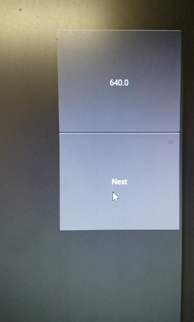
Then we hit next:

We did as the pictures show & the chain fell off, my thought was that in the last calibration I set it to bottom feed so if we do this in reverse then it might tighten & measure, so we did & hit the pull chain again & it worked:

Hit bottom again:

We did this but I think there might have been a problem before this step.

This was interesting, the Left was Right & the Right was Left, but did it, the Automatic didn’t work & hit Set Zero:

Now we have the ring but, above it says from the tip of the chain to the center of the router bit, for us that was 3250mm, we thought & we thought is it 140 mm or what it asked us to measure so we put in the one we measured 3250mm & hit Next:

We did this but again the Left was Right & Right was Left, the chain moved to the point that the sled was in the middle so we hit Next:

The Right side motor just kept going & going till the sled was on the ground, by this time I was getting very pissed of, it has been nearly 12 months since we started this project. This was what the motor looked like when I stopped it:
I went to the next step, then got this problem:

At this point, we just gave up again very, very sh-ty.
Ok guys where do we go from here, do we need to do a total reset of the software & just do it all again, if so what is the best way to reset, please.
Thanks, heeps guys, we need to get this going we have about 10 grand worth of work to cut out, check the sled out in image Cal11 & we have recessed balls on the underside, this is before they went in:
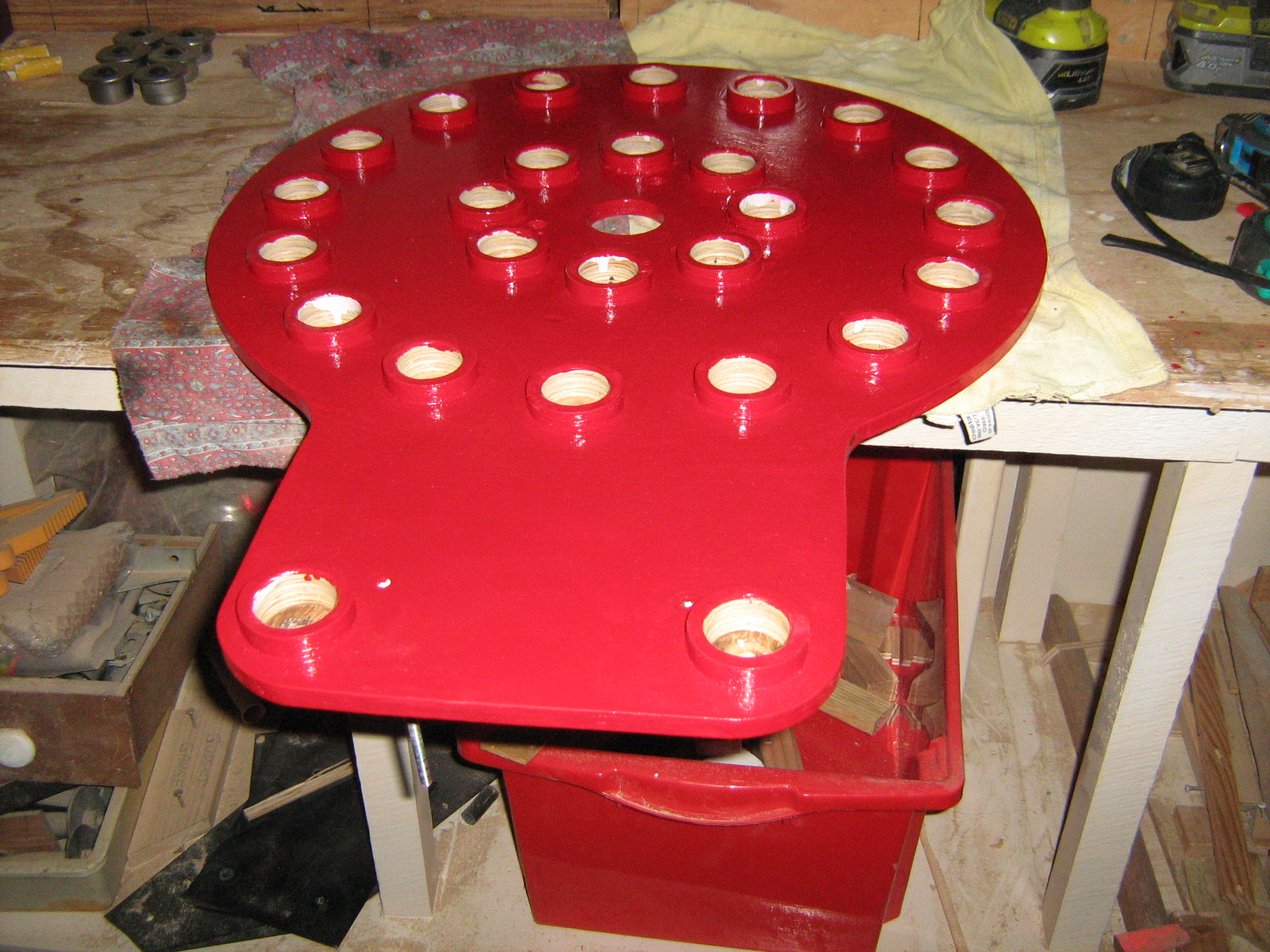
I haven’t seen a sled like this one…
Cheers
Swany & Peter
1 Like
Are you sure you have the motors connected to the correct ports?
http://maslowcommunitygarden.org/Electronics.html?instructions=true
I believe this is the step where it went wrong. For the ring it should be 140. Measure to where the chain connects to the ring

1 Like
Hi Tinker, that is one thing I checked from day one when putting the electronic togeather, I have email Peter who is out where the machine is to take a picture so I can post it as well.

As you see it front on, the Left goes to the left motor, the Right goes to the right motor & the Center goes to the Z access.
So I don’t think we have this wrongly hooked up on the board, & before anyone asked the double-sided tape that was on the heat bars didn’t work so we have CPU heat compound on them & the bands hold them on.
Hi Captain.
I am thinking the same thing…
1 Like
OK, we have done it again & started from scratch, in the next 2 test I run you through I have even deleted the iny file.
I will repost what we di again & the way we look at it is there is a problem with the 2 boards we got…