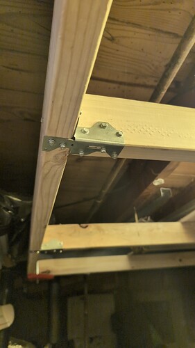
It's impossible for TL, TR, BL, BR motors to be crossed, right?

I built a horizontal frame, my vertical frame isn’t going to work as I built it not knowing that the Maslow needs to be constantly unmounted and remounted.

My old vertical frame I changed the Z order of the spindles for clearance.

I didn’t switch it back as it shouldn’t matter.

I accidentally started calibration in vertical mode, and noticed TL and BR tightening With TR and BL slack. That seems weird, it should have been TL and TR as it was gravity fed…

I stopped it, set it to horizontal, rebooted. Started the calibration process again.

It’s still doing it? Shouldn’t all 4 spindles be tight for horizontal calibration? They’re practically tangling.

The end state has all 4 taught, but it’s saying fitness is like .04. My vertical frame had .70.

There’s no way. Is it somehow confused as to what motor is TR, TL, BR, BL?

I did lower the calibration torque from 3000 to 1000…I can change that but it almost looks like the wrong motors are moving…that seems impossible…you can’t really mix up the controller wires.

I did also update the firmware…I am almost thinking I should re-flash it from the command line… something is super wonky?

Actually, I did get a calibration in on the vertical frame with the spindles like this. So um something went bad with the firmware flash? I did it through the web UI. I can try to re-flash or go down a level through the command line tool instead.

So…erasing and flashing the firmware fixed the weird motor issue.
The orange lights were like solid and dim, and like the motors appeared to be moving out of order. Sometimes the web UI would get stuck saying FluidNC is connecting. Now the orange lights pulse slowly, and the motors are moving in a sane order, and the spools aren’t looking tangled…not sure how that happened. It was persisting across multiple power cycles, firmware immediately fixed it and it’s been power cycled several times.

At 1200 force the fitness is calculating too low - .07.
I set it back to 3000 and it’s back at .27 which is still pretty low but maybe will finish.
It’s just some 4x4s in some sturdy saw horses with 3d brackets to hold bolts and spacers to eliminate the Z axis differential. I climbed underneath and squared it up…I can fix it a little bit better but it’s pretty good…

I am watching Bar’s video
Maslow Calibration Walkthrough 1.05

I didn’t try to pull it so the top two lines are tight. I’ll try that tomorrow.


Cool. So this calibrated to a fitness of .85.
Pulling down on the Maslow per that YouTube video does help. I’m also troubleshooting a temporary frame still.

I realized the Maslow was actually moving the 4x4s in the saw horses until I added clamps.

Once I get this reproducible I’ll post the frame plans.


This is literally heart wrenching
The calibration finished, but really by the tape measure it’s off by like 50mm

I was moving it around the table and again if moving left the right belts get very slack, and vise versa. Why isn’t it keeping them all tight???

I wasn’t watching it and it got tangled.

The belt is ruined.
I cut it but now can’t get it back in the belt end, which I had no issue doing 4 times on the initial build.

This has happened now on two frames, weird movement, and now with no Z offset.

Edit: I got the end on by sandpapering the end of the teeth a little to make more space in the belt end. I think maybe new belt = stiff. The now old belt is much softer after some use and just didn’t want to go in the slot.

But I am very concerned about the movement when I am jogging the device left, and only TL, BL seem to be keeping taught. It almost looks intentional as the device seems to know that it needs to pull in a lot of slack on the TR, BR lines when I jog it right after moving like 1000mm left. Is this intentional?

I think that this might be an issue. The machine is expecting these to be anchored down at the level of the boards surface and I bet that those are going to flex a lot during calibration and throw off the measurements.

Even if I set all the z offsets to 0 in maslow.yaml?
My old frame had them anchored down, the Z offset seemed to cause instability as the machine approached the edges of the 8x4. There seemed to be maybe a 4x3ft area that was OK to cut, the spools got weird beyond that.

If I set the torque to like 3000, they do seem to flex an MM or two. At 1000-1200 it seems OK. They’re pretty thick and supported by two supports each. Even the timing belt stretches though, visibly, so it’s not worse than that…

I am going to try to move it in G code in telnet…I wonder if no one just jogs to the edge of the board and back in the web interface to test movement…?

3000 seems like a very high value - depending on how long the belts are / your frame is, that could be giving you 10mm of belt stretch in itself, whatever the frame is doing. Is there a reason you’re using that much, do you have retraction issues at 1000 or below?

Might be worth starting from first principles - what size is your frame? What size of cutting area are you aiming for / where within that frame are you trying to move it?

Do you have the logs from the calibration runs you can post here (and the settings you used with each one?)?

Ah no you are ahead of me. That is correct with the offsets set to zero. I think that flex is still going to be a issue though.

I can post my calibration values later when I am back this evening, thanks…

I absolutely have retraction issues below 1000. TL binds a bit. It’s just barely good at 1000, 900 it definitely gets stuck pulling in. Guessing it will loosen up over time?
I have it at 1200 now which does function. The vertical frame needed more.

It is calibrating at 1200, but the belts on the opposite side become slack when I move across the frame.

Telnetting in seems to reset the fact that it calibrated and the device will refuse to move - is there gcode to retract, extend, and tighten so I can test from that?

I can post my calibration values later when I am back home.

How I wished this worked:
Manually measure distance between BL-> BR, BR->TR, TR->TL, TL->BR. This is easy and reliable.

Calibration is just the device calculating hypotenuse between BL->BR->TR->BL and BL->TL->TR->BL - easy trig. Assume BL and BR can’t have a Y offset, only calculate skew on the top.

From there it is easy again with trig to calculate the X\Y coordinates of the points in space and not have to use perfect squares or more complex math off-device.

I think the calibration is bunked though for whatever reason here, on both my frames.

Somewhere here there’s a guide to manual calibration…I may try that…

It basically seems to move around fine in the center. I just can’t make extreme movements, like several 100mm moves? Which doesn’t seem right.

I’ve built grbl based laser cutters and a couple 3d printers no issues…

I don’t think there’s sensor issues or connection issues…the calibration process is being consistent and the device is consistently getting tangled after enough movement in any one direction when manually done through the web ui. I have not ever tried to send a grbl file to it.

This is pretty untested so I’m not sure what the behavior is. It might be resetting FluidNC which would cause something weird

It used to work this way, but the number of posts from folks who entered the numbers in the wrong order or messed up the inches to mm conversion was HIGH

You can absolutely do this! @dlang made a calculator to help. You just need to find the coordinates of the anchor points and enter them in settings.

But it sounds to me like there is some issue outside of calibration going on here and the calibration failing is a symptom not the cause.

Have you tried the test for a loose magnet yet?

Maslow-serial(1).log (24.4 KB)
Attached log with calibration…

I have not tested for a loose magnet…I would be surprised…I will look for the test…when I move to the left more than like 2.5-3 ft some of the right cables start getting slack with this calibration…I don’t think it should do that…

Bl to br manual measurement is
2476.5mm

Br to tr manual measurement is 993.775

TR to tL manual 2479.675 millimeters
Tl to BL is 996.95 mm

Bl to tr - 2676.525
Br to tl - 2674.938

I’m a little less confident on the diagonal manual measurement.

Is the calculator available?
I am less confident in my accuracy with diagonal measurements. I think point to point is very easy.

And why not just use fiberglass reinforced belts instead of the steel? And then stop modelling stretch…there’s so much complexity…

1 Like

These are the lowest stretch belts that we can find. They shouldn’t have much stretch at all in them.

I’m working on putting together a troubleshooting guide for some of the most common issues. It’s a work in progress, you can find it here: Troublshooting Guide — Maslow

I forgot I wrote this.
manual_calibration.txt (5.0 KB)

I was going to attempt to port this maslow4 to grblhal instead of fluidnc. I wrote out a sample of what manual calculation of some frame dimensions might look like before giving up. The attached is for p5.js

I just realized maslow is doing this close enough. The script outputs stuff in the order of bl, br, tr, tl. I punched the coordinates in to my maslow yaml and it actually works, no cable slacking. I can move over the ENTIRE 4x8 panel without issue, and with repeatability.

Doesn’t this rule out pretty much everything with the sensors and hardware?

I don’t want to port this over to grblhal, it’s going to be a nightmare with the kinematics, pid loop to make the mag encoders and DC motors emulate steppers…it’s probably above me…I don’t even want to use their ESP driver, the dev isn’t maintaining it for recent versions of the esp sdk.

I can’t make heads or tails of fluidnc though, there’s complex integration between the webui and backend machine state.

Edit: Doing it this way and not via more complex math I think also places a limitation on the Maslow only being able to move straight relative to what it is cutting. It would absolutely not cut square to the edge of the workpiece if the frame is skewed, since it’s assuming that all skew is happening at tr, tl. I think that’s valid though, and the skew would not be worse than the no cut zone with the Z offset issue.

1 Like

I have somehow managed to build two frames that are not compatible with the calibration process somehow.

The first I cannot salvage. It is a vertical frame mounted to the ceiling. Home depot sold me 9 ft boards that were supposed to be 10ft. I saw they were the same length and I didn’t measure beyond that. The bad zone is too large and Z offsets would hit my ceiling. And the mount points are nearly inaccessible as I didn’t know the device needs to be always remounted.

And this frame, I have no idea. Nothing is visibly flexing really. It’s definitely very small, barely larger than 4x8.

And the behavior on both frames was similar, the machine moving erratically outside the center area, z offset or not.

I can’t really use this outside of a science experiment if I have to measure a temporary frame every time I set it up and run it through a calculator. But it DOES move edge to edge now with manual anchor positions put in from my own calculator..

I built the new frame with anchors that are fixed to each part of the frame, but the frame busts down and re-assembly could result in skew, but not anchor distance changes.

I thought I could just re-calibrate every setup but it’s being weird as you see.

I think I HAVE to fork the firmware if I want this to work?

Or is there any other testing I could do to make calibration work? Or can there be an option to have 4 measurements, the length between each anchor point, and the machine calculates the harder to measure hypotenuse and does some math checking? No linear regression, least squares etc. I’m not the only one with the issue, the forum seems littered with people with weird movement issues along the edge of the cut area.

Sorry I am very frustrated…

  • For a temporary frame, recalibrating, waiting for the math - hoping it works - it’s not viable, nor is really complex measurement and doing a bunch of formulas every setup through custom tools…
  • Anyone buying a CNC machine should be able to measure 4 distances, the minimum data needed to calculate anchor points with trig only, and this works better for temporary bust down frames. If something doesn’t work, it’s almost guaranteed to be user error with measurement

The hardware seems totally fine…the kinematics and the motor control…

I agree that those belt anchors look like they would flex. record a video with a stable camera pointed at the anchors while you try and calibrate and play it back at high speed, I’ll bet that you see them moving a lot.

All that the calibration does is figure out what the anchor coordinates are. If you want to carefully measure all 6 distances between the anchors, there are a couple manual calculators (I’ve posted on in onshape, and I saw someone else post one this weekend) that will take the measurements and give you the coordinates (and use the 2nd diagonal measurement to give you and estimate of how good your measuring is by comparing that measurement to what it’s calculated to be based on the other 5 measurements)

I’m not familiar with your journey with the Maslow, so apologies for any of this that’s going over stuff you are aware of!

My take looking at the log and what you’ve posted - your frame is too long and thin, and that combined with very high forces when calibrating is messing things up.

This would work fine if the frame, belts, and unit were perfectly stiff, but they’re not. I wonder if coming from gantry CNCs/3D printers, you’re carrying forward the expectation that as long as you can move the unit to a position on your frame, it’ll work to use that for cutting?

For me, what really helped was the realisation that the closer to a square the frame is, the more accurate it’s going to be - but with rectangular material we compromise that with rectangular frames and keep an eye that we’re not having belt angles that mess things up. And it needs the frame to be significantly bigger than the workpiece to give good cuts.

I found @dlang 's frame calculator a great resource when working out what frame size compromise to make for my work area that has some constraints:

http://lang.hm/maslow/maslow4_frame.html

If I stick in 2500*1000 as rough measurements, you can see that the areas you’re running calibration over are likely to be less than ideal for accuracy.

A quick play makes me think you could either drop the frame to ~15001000 to give you a smaller area but more accuracy in that smaller area, or widen the attachment points to give ~25001500 (or even more) and keep your calibration to a green area.

I think the calibration does a good job of calculating / offsetting skew and the stretch in the system. It does largely come down to being what you might measure but scaled down a little, but you can try approximating that yourself.

And I’ve sanded my spools down a little (What a difference 1/10th of a millimetre makes (how I got retraction to work at force 3/4/500), and I know others have - it may or may not be something that you choose to look into.

As you said, I think both my frames are the cause of issues. But I’ve failed to build two frames, doing it again would be insanity. The first frame the primary issue was inaccessible anchor points, I wanted to leave the maslow anchored and never remove it, but I found out after the fact it doesn’t work like that.

Yes, this new frame is long and skinny - I don’t understand though how that adds to positioning error when the Z skew is eliminated - up to a little before the point that two of the arms are parallel to the anchors like TL and TR, as long as you can measure distances from the maslow to each point it should be able to do trilateration? At extreme angles the accuracy of measurement matters more…but ultimately there’s still two triangles?

It’s not trying to bake the belt stretch into frame measurement, is it?

I am on maslow 4.0, the spool binding…they work fine at around 1000…it’s happening because of play in the motor mount. On one of the spools, the motor is a bit forward and it’s pushing the idler gear and motor gear kinda tight.

Maslow 4.1 the castings were a bit small for the arms and sanding helps with that?

I don’t think the spool binding I have…is the root cause of issues..
My first frame my Z offset was below the spoilboard, so it was extreme.
My new one is long and skinny which puts the TL\TR and BL\BR arms occasionally at severe angles.

I guess in a dire pinch I could lower my ceiling mounted frame and eliminate the z skew with spacers on top to help it move closer to the edges…it’s an accessibility issue, my basement is small…it’s hard to physically get to the anchor points on a ceiling mounted frame…and I have no space for a large horizontal frame which is why the new one is temporary and skinny…

So - what’s going on - is the angle too severe to accurately measure the frame somehow during calibration, but not too severe to move if I punch in the anchor coords manually from my own calculator?

Does the arm at the limit of it’s rotation impact movement? Rectangular frames in general put the arms at more severe angles, and having two legs of a triangle nearly parallel also puts it at a severe angle. BOTH my frames the arms can be at severe angles.

It’s because you’re approaching this:

(from 4.6 Normal, Tension, and Other Examples of Forces – Douglas College Physics 1104 Custom Textbook – Winter and Summer 2020)

It’s the amount of tension required vs the friction of Maslow against the board (if its horizontal) and / or the Maslow weight (if it’s vertical) - and as you increase the tension you also increase the friction and flex.

Again, in a perfectly stiff system with no friction - yes it would just be triangles but that’s impossible.

Explicitly no (though it’s being worked on), implicitly yes - what calibration really is is the amount of belt to put in to move to a specific location. Stretching belts means you pull in less to go the same distance. It’s not perfect, but the calibration reads out a smaller size, so you pull in less, so stretch/flex is offset. It’s kind of like doing 1 * 0.99 * (1/0.99).

That’s why you’re seeing some people that put in laser measured / scanned values then having to apply a scaling factor because the belts are loose. Ultimately you want to use the least force needed to move to minimise all issues though.

Ah, I wasn’t around for the 4.0 Maslow so not familiar - but yeah, sounds like you’d have to do something different to free up the spool more - I think it would be worth looking at for the reasons above, but its a judgment call of course.

I think a woodworking solution is what you need yeah - maybe post pictures (unless you have somewhere else - I know a moderate amount of woodworking, and plenty of others on the forum do too and likely have suggestions.


It’s hard to show in photos. My original frame is like a 9x8 behemoth with hurricane ties. One end is hinged to the floor joists, the other rests on the floor.

I didn’t understand that the anchors need to be accessible for frequent use. My house is 800 sqft and my basement is pretty full.

And in hindsight maybe I want a portable horizontal frame and I can just do this outside. I can barely get 4x8 material into the basement.

I also didn’t originally understand that the belt ends go on top, not the middle.

I can rearrange the basement and go back to the behemoth frame…and try to make the anchors more accessible…that’s probably the sanest thing to do.

At the same time…given that punching the numbers in from my own calculator worked movement wise…rewriting the firmware to more basic math and more gcode sender based is free money wise. I am sick of home Depot runs that result in failure…

I think I can do a PID loop that makes magnetic encoders driven pwm DC motors look like servos for better compatibility…redoing something like a motion planner is way beyond me…

It feels like stretch can be modeled by keeping a running number of additional retraction to keep belt tension. It can be measured diagonally easily at different points along a hypotenuse…

From there, ignored..wouldn’t the belts move like normal triangles if kept tightish? Move slow and just do trilateration.

I might just abandon frame edits and try a port…vastly easier to do things like restore known belt lengths on powering up when you don’t have to sync machine state to a web interface…and if “calibration” is simple math…it can be done on device with custom gcode. I think how I want to use the device ultimately is vastly different from how it is used…

Edit: I am going to go the custom firmware route, and if that fails, edit the frame for the Maslow or build a static cartesian system. Thanks for the informative replies…