Webcontrol should run on osx, but the port 5000 communication is a security issue for those who want to be malicious.
Makerverse may be in the wrong mode trying to move inches while the board is in mm, so it hums trying to go .25 mm instead of 0.25". Humming is good.
What shield version do you have? G20 in the terminal should switch it to inches and G21 to mm. You might start there.
Beyond that, your z axis pitch may be off, so it doesn’t know how far to turn the motor to get a mm of movement. There should be a page in the makerverse calibration to adjust that.
check what feed rate you have set. That sounds like what happens when nothing is
set, it’s moving, but at such a slow speed (1mm/min or something like that) that
you aren’t going to notice it.
Hi there, and thank both you and DLANG for your speedy replies.
So the Motor Control Board is V1.4.c
so now after futzing with feed rates,
Motors 1 and 3 (x and y control) Now actually move when you tell the z to move.
I hooked the oscilloscope up to the PWM motor output from motor two and get the tiniest of voltage spikes at the start and end of those movements, with a 0 nominal voltage in between. all the other pins read normal numbers on the Motor 2 output. so I don’t think it’s a cable issue. and looking at the board again still can’t see anything that would make me think the motor controller is shot.
I’m going to try reflashing on the ‘newer’ firmware found on the main page and see if I get different results.
Whoa ok,
so installed the firmware thats easy to find.
now the z axis is running all the time, and any actions, cause the left motor to let out tension. This is bizzare
So more weirdness continues.
every time I upload the same firmware I get slightly different results:
I can’t find an identifying marker within the code to tell me exactly which build it is.
One result
zmotor on no matter what. left motor moves
upload the same file again,
zmotor no longer moves only left motor moves when any action is selected.
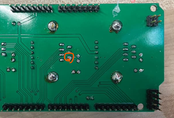
good pictures. Can you tell me the numbers on the chip that is bolted to the heat sink? I can’t quite read it in the upper photo because the chip is vertical.
I ask because I can see the z axis (M2 channel in the middle) uses pins 7, 8, 9 of the arduino Mega I just wanted to verify the firmware matched the chip type and is activating correctly. I’m trying to identify if this is a 5206 board. If so, the firmware should match the chip pinouts. If they don’t match, then that is your problem, but it may just be a double check.
TLE 5206 board version 1.4 checks out. pins on the 5206 using pins 7,8,9 for in2, EF, and in1 respectively for the control pins on that chip from the datasheet line up with output en4, error flag enB, output en3 as described in firmware. It should be fine. The picture shows a weird blob on the solder joint for the positive power pin on the z axis 5206 chip, so check that
but that might be a longer pin out of focus and may not be an issue at all.
Make sure your 12 V power supply is plugged into the shield (upper board) when you try to run the motors or they won’t do anything. Sounds like with the random movement, that isn’t the issue.
The only shield that had issues with firmware upgrading for holey calibration was the easbay 1.5b board and that is fixed in 51.29. The shield you are using has worked in 1.26 on including 51.26 and up.
When makerverse starts and opens the port at 57600 bps, does it show you the settings in the left column below the black background terminal window?
Ok, so I reflowed the board and added on an insulating layer of E-Tape to the bottom side.
Here is the output from terminal on connection
‘Makerverse 1.1.3 [laser] #296 [Maslow]
Connected to /dev/tty.usbmodem101 with a baud rate of 57600
Grbl v1.00
client> $$
ready
ok
client> B05
position loaded at:
-9.00
-32.70
ok
B05
ok’
and when z axis is called:
“G0 Z5
ok
G90
ok
feeder> G91
feeder> G0 Z5
feeder> G90
G91
ok”
Yes, settings look like they should. I see the z axis pitch 3.17 mm/ revolution, so it would make sense that you are using the rigid factory router base. What does your z axis look like? Are you using the std rigid router with the orange tab engaged on the router body? Do you have the bungee over the top? Is the router body clamped, but the bolt on it loose so the z axis can move freely and not bind? Some have even lubed the inner cylinder of the lower router mount to help with the z axis movement.
That’s right I’m using the rigid setup. The socket is clamped- but I adjusted it so it can move with little resistance with minimal deflection undercutting load. The assembly is currently torn apart since I went through and inspected each component. (I rebuilt the gearbox and tested the motor and encoders). So right now I just have the motor plugged into the Control board but not to the machine. There is no movement on the output shaft. There is a bungee over the top to take up the backlash. for when the unit is assembled (if anyone wants my files for the straps i made I’m happy to drop them too.
I suppose I should mention my last job was building CNC’s Lathes and 4 axies out of Bridgeports, clausings, etc. I’m used to mach3 and designing and fabbing mounts adapters and rebuilding the machine. I used nemas back then instead of these ‘servos’
I’ve also received contact from East Bay Source: with a new version of GroundControl and a firmware build. I will test that, though I do hope I can continue to use Makerverse for the bigger community support. Here are the assets they sent me for future users experiencing my chaos LINK.
I find that wasn’t working really odd. The groundcontrol / webcontrol / makerverse are all just senders, sending a G01 Z05 gcode command to the controller to move the z axis up 5 mm. Did you reflash the firmware or just switch the sender?