I’m amazed about how accurate the Maslow is.
I wasn’t sure if the border would work out, but it turned out almost perfectly.
Except for the lighter line on the left, but that’s probably an issue with the marker (or my frame).
I noticed that the lines are not always closing at the exact same point.
Is that something that is also happening when cutting shapes?
It’s not a big issue for me, and something that can be cleaned up with some sanding. Just asking.
I’ve gone through a few iterations of 3d printed plotters so far, and its definitely apparent that if your writing instrument isn’t centered, the output is skewed slightly when the sled rotates around the z axis.
Makes me wish the belt spools were on either side of the router (2 on each), essentially as if they were wrapped around the linear rod supports, so they could hold the sled in the same orientation throughout a cut.
Hi Marzsman, I tried printing the 3MF files posted here but I’m guessing the scale got slightly off somehow… it was very hard to screw together (not smooth like your video, I had to use a flat head even after cleaning the threads up with an exacto) and doesn’t fit in my Maslow sled (maybe 2 or 3 mm’s to large to fit the opening). I will try exporting the bodies from the step file myself now but I figured I’d post this just in case anyone else runs into the same issue. I’m using an Ender and I sliced the 3MF file with Cura standard settings @ 20% infill
I’ve been playing around with a different design that includes a custom marker body. This requires purchasing a spring (from the hardware store), marker nibs (link below), and ink. It is still a work in progress - the STLs print fine and assemble well but I’m experimenting with ink. (It seems ink pad ink is too thin and will run and drip from the marker tip.)
I thought I’d share to spark more ideas and get feedback (especially if anyone has recommendations about thicker ink).
Along with solving the dripping issue with the ink, I’m also thinking about integrating a small compression spring between the router and the pen cap so make it less likely to press too hard into the paper.
I think because of the sled, spring loaded is not needed. All of the iterations I have played with, the spring loaded designs have had too much x/y slop in the tip, making precise plotting or artwork not so perfect. I’ve now gone to a solid pencil and it’s much better…you just have to have the z height/home and your gcode target depth and steps set very carefully, and after a long run, you might have to pause and adjust the pencil downwards so fresh lead hits the surface. (Probably not an issue as much with a pen/marker)
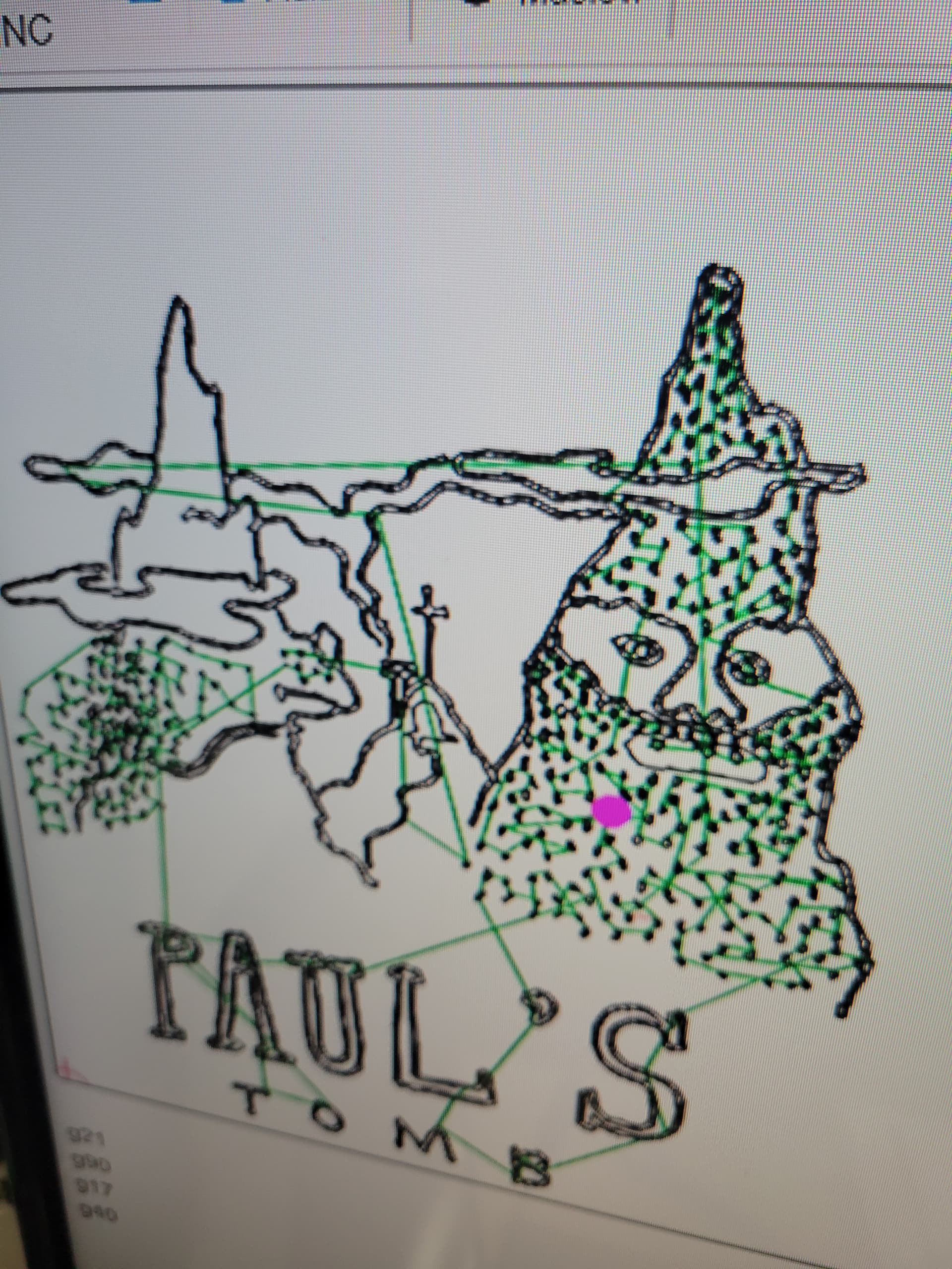
If you can get a spring loaded to work with out x and y slop that’s amazing. Only 1-3mm of tip slop made my drawings/logos on an 8.5"*11" sheet of paper look like kindergarten work. But with stiff tip they come out near perfect.
Below you can see the slop from the computer version to the paper.
Makes me wish the belt spools were on either side of the router (2 on each),
essentially as if they were wrapped around the linear rod supports, so they
could hold the sled in the same orientation throughout a cut.
the problem is that you need them to pivot around the center of the bit, which
is hard to do unless it’s literally around the router (possible, see the earlier
maslow both it’s ring and linkage options) but as you move the weight of the
spool and motor further out from the bit, the more likely you are that their
weight will rotate the arm, causing the belt to not be inline to the bit, which
throws off the position math calculations.
I’m potentially getting it ready to do a “drawing with robots” art night at the local university, where the robot (Maslow 4) does a landscape potentially on large scale and students contribute to the drawing.
Might be interesting, and maybe the “slop effect” could be positive or negative I guess!?
Because I did not have the router yet (I might go with a spindle) but wanted to practice, I made this “router body” on my lathe. A normal marker can be fitted in there, spring loaded.
Great that you are giving it a try!
For the thread, I had to screw the two parts in and out a couple of times, but after that, they fit nicely. Also, be careful not to squeeze the sled clamp while screwing.
Did you use support on the thread? I used organic support, which was very easy to remove. Without support, some of the threads were hanging a bit, making it really difficult to clean up and fit into the sled clamp.
I might have an idea about the part that goes into the sled.
You first have to install that before you screw in the marker holder. This way, the acrylic cover fits into the little inset ring. That’s also why there are two little handles on the side - to squeeze it and make it smaller before installing it.
Then, when it’s installed, you screw in the marker holder, and the two locks themselves in place when the ring is expanding a bit.
I hope this helps.
Tomorrow I’ll try to print both parts again to be sure I didn’t make mistake in my upload.
I wanted to post a video but it’s to large so I made 4 screenshots
IMHO, my lines turned out pretty good.
However, there is likely a significant difference between a fine pencil line and a thick marker line of 2mm.
I suppose that could be the reason why my lines from the start and end don’t align perfectly at the exact same position.
I’ll do some more test and see if I can find a way to reduce the x/y slop.
I thought about it and decided to use markers. Also, there is an issue with markers drying out when they are exposed to air for too long.
Thanks for the suggestions! It does fit without the pen holder screwed in (I didn’t bother reprinting after checking the model in Fusion and my measurements match your design). I printed with standard supports in Cura - the tree support generation wasn’t consistent so I used the standard ones for this. I’ll keep working on the threads - you can see in this pic they came out a bit like a ratchet gear on my printer, I’ll take a Dremel to them and see if I can get it working smoothly. Hopefully the everyone else’s printer just works with your original design. I built my Maslow a week ago but have not completed a frame built yet, hopefully I can get that built and test this over the weekend.