@superbender: Here’s what a quick workup of the design mods you suggested. At 55 degrees it will interfere with the feet unless I either reduce its diameter or put an upwards angle on it.
@rwales: Thanks for looking into this and helping me figuring this out.
I received the scad file and will start looking at it. I hope I can do something with it and it isn’t too complicated.
The first comment that I have with regards to your quick drawing is that the tube stub seems to be a tad short. I you insert a vacuum tube or extension, the it will protrude into the ring area, which is not good. We should lengthen that tube stub section.
I made a few tests and added some mockup pictures with different angles from 55 deg to 65 deg.
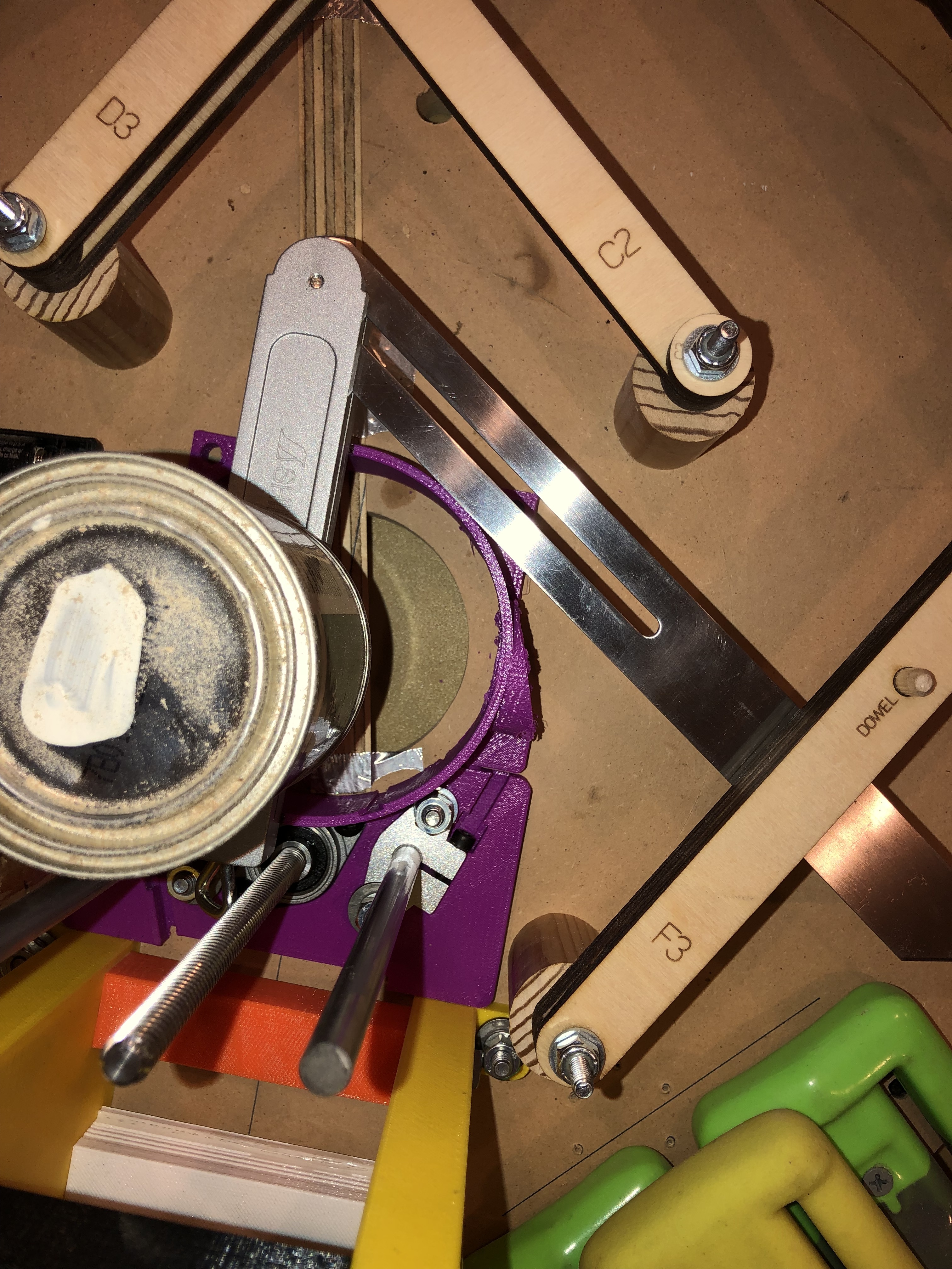
The first image shows the ring with the original dust tube cut off. The silver angle adjustment thingy (which is held down with a can) is set to 55 deg and tangent to the ring to move it as far from the z-axis base as possible. In the second image I am adding a piece of wood that is about as wide as the dust collector tube. The tube would clear the linkage kit post, but I agree that there is some conflict with the already installed z-axis base. So, 55 deg may not work.
I then increased the angle first to 60 deg and then to 65 deg. I think it would be best to keep the angle as low as possible since gravity pulls the vacuum hose and turns the sled a little to the right when cutting. I might be off of course, but intuition (and some basic physics) tells me “the lower the angle, the less the effect”.
At 60 deg, I seem to clear the z-axis base, which again requires the tube to be put as far from the z-axis base as possible.
At 65 deg, we get even more clearance and we might even avoid my weights. But I rather rearrange the weights to keep the sled as “straight as possible”.
Move the tube as far away from the z-axis base as possible (i.e. as far up as possible)
Lengthen the tube so that the connector tube does not penetrate into the cutting area
Also:
I expect I need an extension tube that runs from this dust collector ring to the sled edge where the tube which increases in diameter will be connected.
I think that all makes sense. I got a little hung up on “lengthen the tube so the connector doesn’t penetrate…”, but I believe you mean to lengthen the amount of room provided for the hose to insert into the hose connector, thus reducing how much of it sticks out, etc. Let me know if that’s a correct assumption.
I have a working re-do at 60 degrees, I think.
(potentially boring digression; skip if uninterested)
I actually was having a hard time figuring out what 60 degrees is relative to your measurements, as when I was adding degrees to my model it was making the angle more acute, not less. Finally I reasoned that, if 90 degrees on your measurement would be straight out to the right, then 60 degrees would be 30 less than that. Anyway, that’s what the model is based on.
(end boring digression)
That has a 1.5 cm segment on the hose connector where you should be able to insert (and zip-tie secure) a 1.5" hose. I could lengthen things more, of course, but this is a starting point. (I’m also thinking about including a screw-down block you could attach to a sled to brace the free end of the hose connector against. It would reduce the forces on the neck of the connector, which would be good.)
I have this as a printable STL file if you’re feeling brave. I’ll email it to you on spec, but don’t feel compelled to print it if you still see tweaks you think ought to be included. No sense spending 5-7 hours printing something if there are other mods still pending.
Let me know what you think of this revision and, if you do print it, let me know how that works out, of course. If we get this nailed then I’ll include it in the kit as an alternate dust-shroud for folks who need it.
@rwales: Thanks for the latest design. As I said in my email, it all looks good. I cannot find a flaw.
I just went back to my sled to check the height of the linkage kit. The tube should not be higher than 4.5 cm from the sled surface. That would allow it to pass with a few mm of space to the moving parts of the linkage kit.
I think I’ll move forward and print this in the next couple of days and install.
Once that looks good I might have to (a) move my weights and (b) make an adapter tube that reaches to the edge of the sled. As you suggested, this one could have some brackets/flanges that attach to the sled to make it nice and stable.
Will keep you up to date.
OK. I also realized that this new shroud will either require it’s own dust sleeve (the upper part that slides over the shroud) customization, or you’ll have to go without the dust sleeve with this alternate design. I suggest you just don’t mount your front dust sleeve for now (you actually might have to take both off, but it looks like the back one won’t interfere) and we work out the rest of the design. Once that’s settled I can figure out an alternate dust sleeve design that marries with the new shroud design.
Update.
Some success, some setbacks. Here is my current status:
The dust shroud seems to be fine. I installed it and is fits and clears. I needed to push it a little so the outer shroud that comes from the top slides by it. I just pushed the shroud a little to the side when fastening it on the sled and it seemed to work.
The base mounting nuts prevent the maximum depth of the router right now. See picture below. I don’t think that matters much though, but some more cutting depth could be gained if needed. It could be that other conflicts exist (at the dust collector tube?), but this is the first one that kicks in.
The clamp is too wide. Seems like my clamp is a tiny bit too wide. It does not clamp. I can still move the router around after the surfaces connect. (And yes, I removed all the grease.) Not perfectly sure what to do here. I could imagine to put a sticky material between the clamp body and the router such as (i) non-slip drawer liner, or (ii) strong double sided tape. The third alternative would be to measure really carefully and reprint with a scaling factor to get it to fit. Could be a precision thing of my printer. Suggestions are very welcome.
I have cut the front top dust shroud with my scroll saw so that it clears the new dust collector tube. I think that will do for now. Once I get my clamp going I’ll try it out and make suggestions to design a real part.
All in all, I have to give many compliments to @rwales and supporters (minions? ). Excellent built, well thought through, lots of attention to small details and making a really good impression on me. Somebody has some good OCD going there. Keep it up.
Just a few little things to overcome for me to be in business.
All those issues are familiar to me. Here are my suggestions / thoughts:
On the shroud / dust sleeve clearing each other. Yes, the tolerances are kind of tight, and that makes it important that the shroud be mounted as close to dead-center relative to the router position (which is ultimately defined by where your rods base got mounted) as possible. Sounds like you’ve got a solution. I remember in one iteration I had to go in after dry-fitting and sort of widen-out the shroud mounting holes so I had room to move it a millimeter or or so to the side. So what you are doing sounds about right there. Long-term I had gotten a suggestion from @pgudat to maybe include a hole-drilling template in the kit. I think that shouldn’t be very hard to do, so it’s an enhancement I’m thinking I’ll do when I get time (and/or it becomes more compelling).
On the base mounting nuts, yes, it is possible for a long nut to steal some of your z-axis range-of-motion, but as you said, it probably isn’t affecting anything in practical terms. Even at its highest mounting point you would have room (unless you were using a pretty short bit for some reason) to get fully through a 3/4 depth before that ought to interfere. But maybe somebody wants to have 1" of range, or maybe there are short bits out there to be thought about. What I did was to replace that bolt with a shorter bolt. (In reality I didn’t have a short enough bolt so I cut it down with a hacksaw. Just be sure to place two nuts on the bolt before cutting so that you can “repair” the threads by removing the nuts. You can also file a little taper onto the bolt post-cutting to ensure you can still thread a nut on it.) Finding a low-profile nut and cutting your bolt as flush with that as you can would also give you back a little room.
Also related to this, my finding is that the best place to mount the router to get the most cutting depth is with about 1" of the router body showing underneath the bottom clamp. That, combined with taking care of the bolt issue, should give you the full range of motion, which ought to equate to about a full inch of cutting depth.
This is a funny one. My first half-dozen or so clamps were tight as heck with just plastic on metal when fully bolted down, but something in a recent revision may have introduced something into the model. My last set of clamps on my own build did have a wee tiny bit too much room. What I did was to find an old bicycle inner tube and cut some of that material to line the clamp with. You could either fully line the clamps, or just glue 3 or 4 squares on each half, either works. Under clamp pressure, those will make the fit tight again. (In a pinch, I think 3 or 4 layers of kitchen plastic wrap or a cut-up ziplock bag would even work.) I will go into the model, however, and add a half millimeter all round and see what that does. I’ll post when I upload those modified files.
Yeah, we had anticipated that the dust sleeve clearing the new hose placement was going to be a problem. Should be easy to design around that.
And thanks for your compliments. It’s been a fun design project, and all the ideas and contributions from the community make it all the more fun to do. I can’t wait to hear how it works for you when you get these last details sorted.
@rwales: I found some time to get back into the garage and work on those issues.
I didn’t find it that hard to make the dust shroud fit. Not sure if the complexity of a drilling template is worth the time required for the install. In my opinion assembling it last and fastening it with some beefy screws from the top that do not penetrate the entire sled seemed to be working well.
Fixed. I used a shorter screw, moved the spring washer to the underside of the sled, and used two leftover square nuts which were much thinner. It doesn’t seem to be a limitation any more after I mounted the sled as you described in your post.
I used two strips of a soft rubbery stuff that I had laying around on the two outside clamp portions (purple). The yellow clamp portions seemed to be a little tighter. Anyway, got it together just fine and nothing is moving.
Picture from my “adjusted” dust sleeve attached. Sorry about the bad lighting. I’ll have to wait until the weekend to test it out, but I hope it will work.
I also did:
adjust the pitch for the z-axis in GCode to 8mm and it worked well.
Other than that, I still need to:
Rearrange the weights at a minimum on the right side.
Design and print an adapter dust tube to allowing connecting to my hose. => Could you send me the dimension you used for the dust tubes? That would save me some time I think as the original dust tube connected well to my hose.
Test it all.
And then last not least I would like to:
Come up with a motion stop system when the sled is too high or too low. I probably would put out an independent thread for that, if others are interested to pitch in.
Feels like I got a lot accomplished with your help in just a couple of weeks. Great feeling. Can’t wait to make shavings again. Thanks for the great support.
Tschöhö
Superbender
P.S. I have the original dust shroud that I can volunteer to anybody who wants it.
On the hose connector, the inside diameter should be 1.5" exactly.
Also a question for you: From your pics it looks like the back portion of the dust sleeve (the one that gets permanently mounted to the lower ring clamp) must clear the new hose design without modification. Can you confirm that it a) clears fine without modifications, and b) doesn’t need any compensating adjustment (i.e. needs to be widened, for instance)
Can’t wait to hear about your first cuts with the new rig!
Router body clamps:
I’ve figured out what happened with the loose router clamp issue that was reported. Indeed, I had inadvertently added a millimeter to the inner dimension of the clamps, which was just enough to make the router slide a bit even when the clamps were fully tightened down. (Note, if this has happened to you, you can either grind a bit of material off of the ends of the clamps where they meet each other, or easier still, line the insides of the clamps (where they contact the router body) with something rubbery like an old cut-up bicycle inner tube or similar. Just make sure it’s not too awfully thick and it should work fine.)
Anyway, I’ve posted updated STL files that take care of the issue and should make the body clamps nice and tight without the need to line the clamps with anything. If you download the files now you will get the redesigned clamps.
Dust Shroud Alternate Version:
The alternate-version dust shroud / dust sleeve that @superbender helped me work out are now posted as well. The model files are in the “Individual Parts” sub-folder, and should be substituted for the original dust shroud / dust sleeve when printing your parts kit. I also updated the build instructions with a note to identify the correct parts before you start printing your kit.
I’m playing around with my own 3D printer (like one new tech toy wasn’t enough ) and generating these parts.
I had a friend run some off and a couple came out better than others. I’m reprinting some.
A few questions though, forgive me for being a newby at 3D printing. BTW Anycubic Mega - S, Inland PLA+, Cura for slicing and running the printer
What tools do you use to clean out the dust chute? When I print it, the support is end to end and difficult to remove. Is it possible to modify the supports that get used/created?
The current dust chute I have does not fit well in the lower Z axis support block (Rod base?) The base of the chute seems to be a bit thicker in the are where the 2 parts come together. Or do I have a scaling issue with on part or the other?
The Motor brace came together very nicely.
I’ll post pics as I get it set up
On the supports, I always select “supports on print bed only” instead of “supports everywhere.” I am using Slic3r, but Cura ought to have equivalent settings.
On the dust chute not fitting, I assume you mean the shroud (the lower piece that bolts to the sled)? Those should line up pretty well using the pegs supplied, but you might have to clean up the pegs and/or the peg holes after printing and before assembling. But pics might help me understand the issue here.
I do recommend printing all parts using the same settings on the same printer as much as possible. It is definitely possible for a different printer to scale a part up or down slightly, and as small as the tolerances are for some of these parts, that could make a difference.
If you are talking about where the dust sleeve (the part that moves up and down with the router) meets the dust shroud (bolted to sled), then a couple of thoughts:
The clearance between those two with a correctly assembled setup is only a millimeter or two.
If you do have a scaling issue, it might eat up that clearance and make those parts rub.
But so will it if you don’t have your rods-base centered and your motor brace assembly correctly oriented to that (with its own alignment pegs). Try unbolting things from the sled and see if you can get things to line up with nothing bolted down to see if that’s the problem.
I’ll check in later to see those pics and maybe that will spark additional ideas.
No pictures yet but I did figure out the dust shroud to rod base issue. There is a piece of the dust shroud skirt which is adjacent to the rod base that is actually support and is meant to be removed.
I was redoing the shroud to try and keep the dust port empty and noted that the initial layers were not solid/complete like the rest on that side. I tried breaking that off and voila perfect fit.
I’ll have a good set of parts by the end of the day and I should have the whole thing on my sled and working by Monday.
Looks like I am there.
I printed the last tube and hooked it up. It went ok. My dimensions were not perfect and the end broke off the piece that was supposed to be somewhat flexible. Printing upright put some natural break lines in there, so maybe printing flat would have been better.
Anyway, I started with some test cuts and it seems to work.
The thing I do not like is that z-axis zero adjustment is difficult and when the system is cutting I can’t really see anything. It’s all by ear from now on I think.
Kudos again to @rwales, thanks for putting it out there. I can’t wait to work with a reliable z-axis.
Looks good.
I’m almost done printing a ll the parts for mine. A couple of minor mistakes had me reprinting parts. I’ve learned a fair bit about my printer and the filament I’m using. I hope to have the Maslow up and running with this router support/Z Axis in a couple of days.
I now implemented the automated z-axis adjustment.
That addition makes things way easier and there is no need to see the bit during z-axis zeroing anymore.
Awesome. Here is one of the threads that I used.


 ) and generating these parts.
