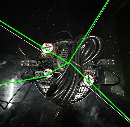
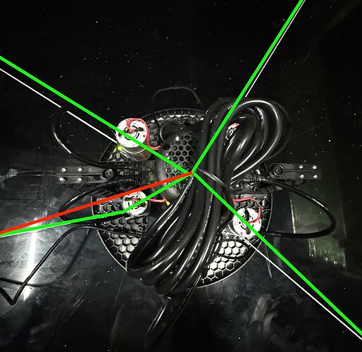
Well I’ve got 2 sets of anchors gluing overnight roughly 16" inwards. Will test tomorrow sometime.
Unfortunately @ronlawrence3 tried a different dimension frame and still had the same issue so I’m not holding out too much hope…100% worth a shot though.
I’m continuing to rack my brains for what it could possibly be.
Well that’s unsettling. .
Fitness: 0.03799018695177388 in 2100 cycles
CLBM:[{bl:2127.20, br:2110.37, tr:2166.13, tl:2168.68},{bl:1881.07, br:1883.28, tr:2469.55, tl:2446.04},{bl:1113.03, br:2726.52, tr:3212.11, tl:2013.47},{bl:1953.43, br:3217.92, tr:2800.34, tl:1119.73},{bl:3224.89, br:2011.66, tr:1114.82, tl:2743.40},{bl:2799.66, br:1116.55, tr:1990.80, tl:3215.59},]
Maslow_tlX: 40.5
Maslow_tlY: 2319.2
Maslow_trX: 3728.6
Maslow_trY: 2186.0
Maslow_blX: 0.0
Maslow_blY: 0.0
Maslow_brX: 3657.3
Maslow_brY: 0.0
However having made the frame smaller I did notice something on the last point.
I think that you are right that is an issue and when we fix that things will be better, but mine does that too ![]()
I think that is the kind of thing which takes us from a 0.8 calibration to a 0.7 but I don’t think that could take us to 0.02.
I am going to work on trying to make the calibration work with just three belts (I think it is possible) and then run the numbers for each set of three belts and see if we can track the issue to just one arm.
I was also wondering (I literally had a dream about your calibration issues last night ![]() ) if it might be worth fully wiping the firmware and starting fresh in case there is some funky configuration bug.
) if it might be worth fully wiping the firmware and starting fresh in case there is some funky configuration bug.
If you have a chance and a USB cable, can you run the “Full Install.bat” in this folder with the USB cable plugged in and the machine powered on (It needs the power-supply connected to program)?
That will fully erase your board and reset everything to factory defaults.
Edit: File was too large to upload, working on it
Edit2: Here we go: Full Install — Maslow
Plugged it in and ran the full-install.bat and chose the correct COM port, updated the maslow.yaml with my frame dimensions, and ran a 4 point calibration.
CLBM:[{bl:2296.37, br:2412.05, tr:2316.72, tl:2184.72},{bl:2032.97, br:2014.58, tr:2659.47, tl:2653.66},{bl:1215.72, br:3067.30, tr:3443.18, tl:1973.49},{bl:2140.39, br:3499.19, tr:2984.26, tl:1112.73},{bl:3402.57, br:2054.95, tr:1237.46, tl:2974.89},{bl:2964.42, br:1203.73, tr:2113.55, tl:3410.32},]
Fitness: 0.04656376585675516 in 2600 cycles
Maslow_tlX: -34.9
Maslow_tlY: 2173.3
Maslow_trX: 3990.2
Maslow_trY: 2316.2
Maslow_blX: 0.0
Maslow_blY: 0.0
Maslow_brX: 4019.2
Maslow_brY: 0.0
Index.html Version: 0.67
[MSG:INFO: Firmware Version: 0.67]
[MSG:INFO: Motor detected on Top Left]
[MSG:INFO: Encoder connected on Top Left]
[MSG:INFO: Magnet detected on Top Left]
[MSG:INFO: Motor detected on Top Right]
[MSG:INFO: Encoder connected on Top Right]
[MSG:INFO: Magnet detected on Top Right]
[MSG:INFO: Motor detected on Bottom Left]
[MSG:INFO: Encoder connected on Bottom Left]
[MSG:INFO: Magnet detected on Bottom Left]
[MSG:INFO: Motor detected on Bottom Right]
[MSG:INFO: Encoder connected on Bottom Right]
[MSG:INFO: Magnet detected on Bottom Right]
I could be way off here, but I notice in your video the bottom left arm has also run out of angle like mine does (I also have a large-ish frame, 4000mm wide)
Does the calibration correctly account for the "extra’ belt length due to the bend at the rollers?
for reference, what is the frame size you expect?
This is ~13’x8’ and that is too wide, you don’t have the angles and so the arms
are going to be hitting the frame at the top and bottom centers, giving you
inaccurate results.
David Lang
no it does not, that will result in readings that don’t match the others.
but doing a smaller pattern may avoid hitting the stops
David Lang
It does account for the bend at the rollers. The distance measured is the distance from the roller and then we add a constant to that since the distance to the roller is always the same
I have a few cells in this sheet to give you the angles (around U22)
the angles need to be >20 degrees
I’m working on doing something better, but haven’t gotten around to it yet.
What I think we need is two options.
-
“this is the size workpiece I have, what frame size works”
-
“this is the size frame I have, what size workpiece can I use”
I really want to try and do this with graphics to show the safe area
David Lang
even though the distance from the spindle to the anchor is different because of the arm hitting the upright ?
Oh no I misunderstood, that is not taken into account. If the arm is hitting the upright that will impact the measurement. @dlang had it right.
I’m 99% sure that isn’t causing the issue that we are seeing here though with getting results like 0.04…I think that will have an impact, but not to the extent that we are seeing.
I could be totally wrong though.
The way to test that would be to run a smaller grid say 600mmx600mm so that it’s not a concern and see if that works the way that we would expect it to.
that assumes that the arm is in-line with the belt. If the arm has hit the
frame, instead of that being a simple addition, you have two arms of a triangle
and don’t know the angle or 3rd size so you cannot possibly account for it.
David Lang
I just posted a topic thead about
that checks the workpiece size and offset to tell you if the angles work or if
you will hit the frame.
David Lang
OK, I think that I am on to something here.
Recomputing the process using just three belts at the time gives us:
TL Removed - 0.64
TR Removed - 0.78
BL Removed - 0.011
BR Removed - 0.022
I was kinda hoping that three of the four options would be bad and one was good. That would indicate that if we take away one arm everything works right so there would be an issue in that arm. IE, if we removed the data from the top left arm and everything worked out correctly then it would be safe to assume that the data from the top left arm was the issue.
This on the other hand makes less sense…but I think that it is still progress.
I am going to keep digging.
This was computed with the data
After sleeping on this those results make perfect sense.
We declare that the bottom left point is always (0,0) and that the bottom right point is always (?,0). This anchors our coordinate system.
Ie when we say another point has coordinates (3000,2000) those numbers a referenced in terms of how far they are from that (0,0) point that we picked.
When we remove either of the lower belts measurements from the calculations we are removing our anchor points for the coordinate system so we are left floating around.
It seems very positive to me that the results from the other two are 0.6 and 0.7 which are right on for what we expect.
This is feeling like a math issue to me. It seems like for some reason we aren’t converging on the correct answer.
I am going to dig more into the math today and see what else we can learn.
Playing around with this some more I was able to get to a fitness: 0.319 by running the calculation first ignoring data from the top right belt to compute the coordinates of the top left anchor point and then doing the opposite (no TL) to compute the coordinates of the top right anchor point and then plugging the those values by hand back into the system to check the fitness.
This is obviously clunky and doesn’t work well, but what this is telling us is that our system is not finding the best possible solution.
When we run our system on the full set of data it is telling us that the best possible answer has a fitness of 0.02 when I have come up with a different set of coordinates with a fitness of 0.319 by a different technique.
Basically our math is not always finding the best possible answer. I’m not sure why or under what circumstances this is happening yet, but it seems like we’re gradually eliminating any sort of hardware or settings issue and this seems like a pure math bug to me.
Next step is to squash it!
OOO I was able to get all the way up to Fitness: 0.497 by using my hand computed anchor point locations as the starting values and then incrementing the system from there.
The problem is that it didn’t stop automatically…it kept “improving” the anchor point locations all the way back down to 0.02 or something if I left it to continue running.
That’s not the behavior we want!
Hey that’s looking better! The math is beyond me.
Just updated to 0.68.0 and still having the same problem.
[MSG:INFO: Point: 0 (0, 0)]
[MSG:INFO: Point: 1 (0, -500.000)]
[MSG:INFO: Point: 2 (-1000.000, -500.000)]
[MSG:INFO: Point: 3 (-1000.000, 500.000)]
[MSG:INFO: Point: 4 (1000.000, 500.000)]
[MSG:INFO: Point: 5 (1000.000, -500.000)]
CLBM:[{bl:2294.71, br:2413.40, tr:2316.81, tl:2184.73},{bl:2032.90, br:2014.50, tr:2662.33, tl:2656.59},{bl:1216.10, br:3064.67, tr:3440.95, tl:1973.60},{bl:2138.76, br:3499.28, tr:2984.26, tl:1112.77},{bl:3403.64, br:2054.86, tr:1237.68, tl:2984.49},{bl:2964.41, br:1203.82, tr:2114.14, tl:3410.85},]
Fitness: 0.04923842460892344 in 1600
WARNING FITNESS TOO LOW. DO NOT USE THESE CALIBRATION VALUES!
Calibration complete
Calibration values:
Fitness: 0.04923842460892344
Maslow_tlX: -16.8
Maslow_tlY: 2186.0
Maslow_trX: 4016.6
Maslow_trY: 2279.0
Maslow_blX: 0.0
Maslow_blY: 0.0
Maslow_brX: 4028.6
Maslow_brY: 0.0


