First I removed a factory lead screw and plastic fixture - it was wobbly, hard to turn and allows loose movement of router. Thread is 4mm, way to coarse for z axis.
I think that the same router is sold in US/Canada under the Ryobi/Rigid name: T8 lead screw with washer is available on the net for example http://bit.ly/2FzCfZK
If you like it I can send you stl files of washers or let mi know how to make it available in our forum.
Sorry Gero - I do not quite get it ;-(( As I understand I have screw with one lead, 2mm pitch, giving travel 2 mm per rotation. That value I’ve entered to GC. I hope that I am not mixing something.
I don’t have the AEG router, nor the Ridgid. I may be wrong. The default setting is 3.17mm. If you have 1 lead, you slowed it down a bit. With 4 lead you could have a bit more then doubled it, I think.
If I read @Gero 's link correctly, it might be possible to have up to 14mm per turn just by swapping the screw and the nut? That would be a very compact translation amplification! When amplifying tough, I wonder how much the router base mechnical drag could still be overcome with the stock Z motor and arduino shield H-Bridge.
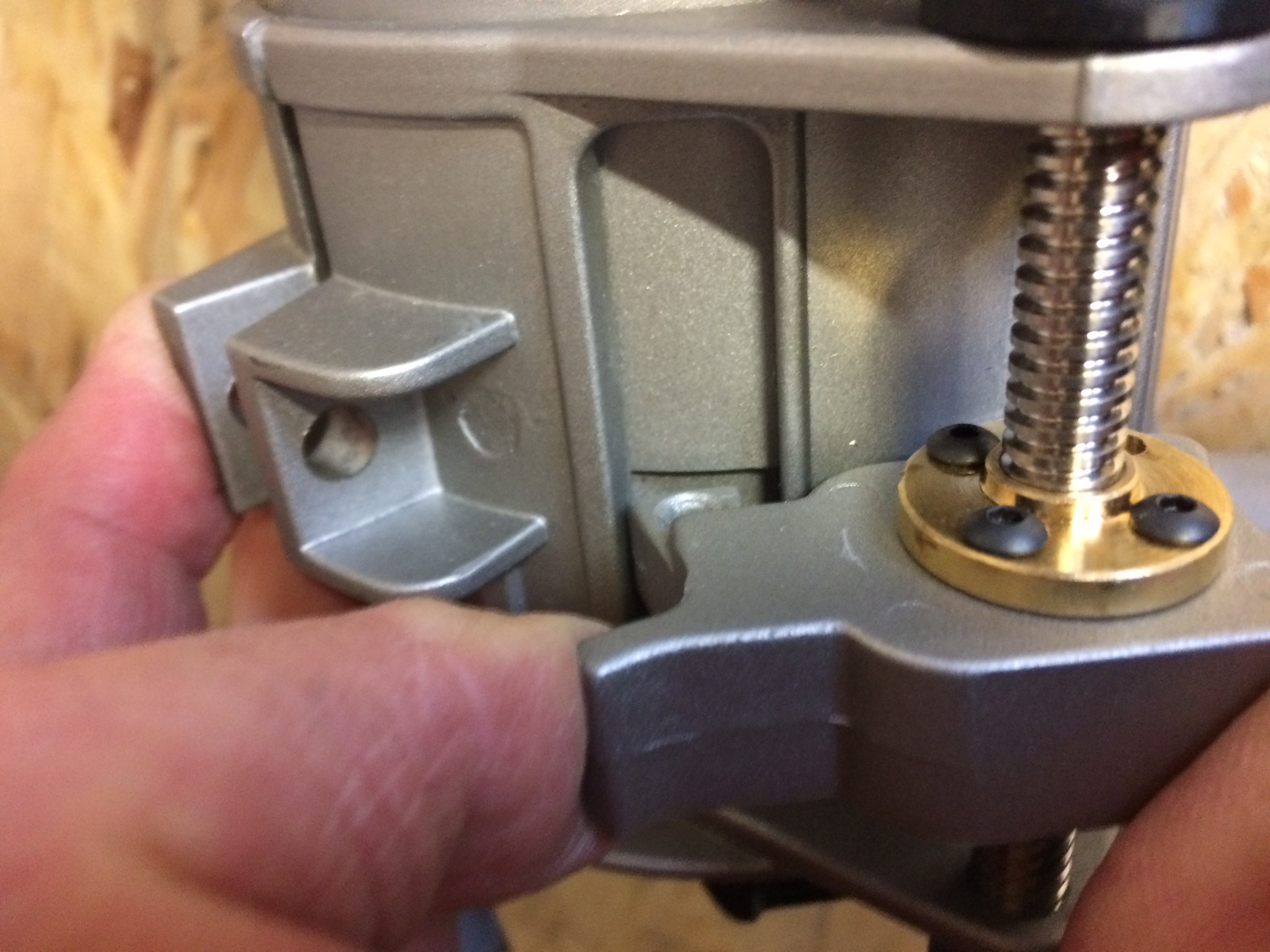
Note: I have the Rigid (Ryobi) canadian edition. I did setup a screw with a modified C clamp.
Note the brass bushing to get a snug fit and prevent frame wear. Sliding the bushing to remove it also allows the screw to be pulled and tiped out of the frame for (dis)assembly.
Was quite a machining job and yet have only 2.5mm per turn. It is very reliable but I am definitely looking for a faster solution.
How many s can I give this post? I have been trying to catch your bearing idea for quite a while! I wish I could see the clamp more clearly. How easily does it detatch for maintenance?
Release is a snap: pinch the paper clamp, let the bearing slide 1/8" along the axis and the pry bar is released, the router body slides freely.
The pry bar is then loose. It is a modified spade drill bit pinched between a custom keying tab and the cut C-clamp body.
The Keying Tab is a general particle board anchor I found at the hardware store, then milled to fit snugly into the router body key slot.
Additional note: I also waxed the sliding body surfaces to reduce friction. And I use the tube cap trick with bungee cords to keep avoid backlash: (Showing here the chain snap protection simulation)
I am loving @TomD 's topic and @c0depr1sm 's input.
As much as I would like to build a meticulous z axis I feel like this is more my speed using what I already have to its best capacity.
Honestly I’m tempted to use an old Black & Decker router that has rack and pinion depth adjustment on it with a knob that could be replaced with the motor. What do you guys think?
When seting up my Z axis, I came to a point I wanted to replace the motor/gearbox to increase speed. I needed to measure how much torque the gearbox has to overcome. That is because these things are sold from catalogs listing speed and torque.
I later considered it was a bad idea to increase motor size with higher electrical current load on the shield. That is because there is only so much power the genuine shield can handle. At the risk of overheating.
Coming back to torque: I wanted to measure the needed motor torque. So I disconnected the motor/gearboxx from the shaft coupler. I wrapped a wire around the shaft coupler and attached a bottle filled up of water to try to figure out how heavy the bottle needed to be to start turning the router screw.
There is some initial torque (static friction to overcome), then it can move with less torque. In my case it was in the order of 2.7 kg.cm. Barely turning.
That is why I carefully waxed and adjusted the router clamp latch to not hold the router body and yet not let the router body move sideways (affecting the bit position).
Now that screw thing above is definitely something I want to try tuning.
Note: On the picture of your router base, there is no clamp. In my experience with the Rigid, I needed to use it and adjust it carefully to prevent the router to move laterally or vertically into the base during operation.
I actually removed the clamp from mine and replaced it with a nut and hex head bolt. This way at I can just use an Allen wrench to adjust it instead of the painstaking OPEN THE CLAMP, ADJUST SCREW, CLOSE CLAMP, OOPS TOO TIGHT, OPEN CLAMP, etc. Can you tell I got annoyed? Anyway it’s just a part of the evolution of my machine. It’s way easier now.
I really like your modification for the Z-axis and I am going to try it myself on the Ridgid router. I’m working on getting a T8 lead screw ( 4 starts, 2mm pitch). I printed your STL files over the weekend,but noticed in the picture you have printed a motor support, but did not include it in the Community Garden.
Anyway you could upload the file or did you find that it didnt help?
Motor support didn’t help at all - the Maslow’s z- kit metal bracket is good enough - I did not bother to upload that part. It is left over from my previous Bosh arrangement and I included it in my current design even if it is too short as you see - sorry for confusion
Tomasz
also…
make sure that you have a ~0.5mm clearance between router body and Maslow’s black bracket. I did grind a little to make sure that lead axis and motor axis are coaxial and vertical - less stress on coupling.
I am happy to report that I ran my first job with the modification to my Ridgid R2911 with @TomD’s 3D printed parts and a T8 lead screw with 8mm lead and more than doubled the speed of my stock z-axis as @Gero mentioned earlier in the thread!
Note the coupler in this kit is 5mm to 8mm. So, I ended up drilling out one end out to 6mm to fit over the stock Maslow Z-axis motor shaft. I also took apart one of the pillow block bearings bushings to secure to the bottom of the screw with allen screws.


 s can I give this post? I have been trying to catch your bearing idea for quite a while! I wish I could see the clamp more clearly. How easily does it detatch for maintenance?


